Download
1 / 23
230 likes | 347 Vues
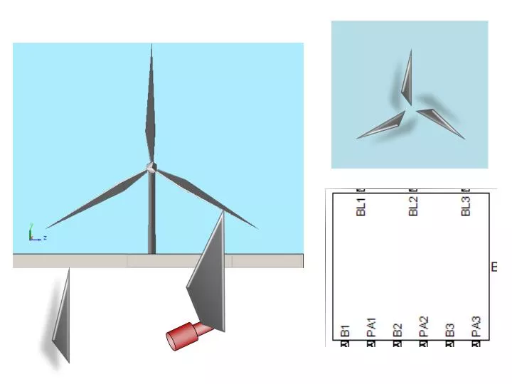
B. A. Output (Force). x. Input ( Valve Displacement ). Tank. Pump. Code. X. S1. S2. S3. X. Calculating Blade Loads. Lift = 0.5* v 2 *Area* ρ *C L Drag = 0.5* v 2 *Area* ρ *C D Where C L &C D = f( Angle of Attack ). Lift. Drag. Rotation Wind = Rotor Speed( ω )* radius.

E N D
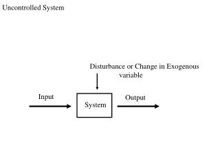
B A Output(Force) x Input(Valve Displacement) Tank Pump
S1 S2 S3
Calculating Blade Loads Lift= 0.5*v2*Area*ρ*CL Drag= 0.5*v2*Area*ρ*CD Where CL&CD= f(Angle ofAttack) Lift Drag Rotation Wind = Rotor Speed(ω)*radius Positive Pitch Angle (θ) InflowAngle Pure Wind(Vinf) α ResultantWind Angle ofAttack(α) InflowAngle PitchAngle = - Pure Wind Rotation Wind = atan
ControlStructureforPitchControl ControlStructureforPitchControl Pitch AngleCommand ValvePosition Desired AngleofAttack DesiredRotor Speed + Control Control - InflowAngle ActualRotor Speed Limit PitchtoStable Region
ControlStructurefor Yaw Control ControlStructurefor Yaw Control Yaw RateCommand TorqueCommand YawCommand Control Control Limit Rateto 0.5 deg/s Nacelle Yaw Angle Nacelle Yaw Rate
Pitch Wind Blades Geartrain Generator Hub Yaw Tower Grid