Download
1 / 44
440 likes | 535 Vues
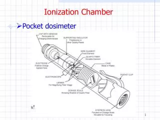
LBNE – LAr-FD Time Projection Chamber detector illustrations LBNE-doc-2794. Updated June 20, 2012 R. Rucinski, S. Hentschel. LBNE LAr-FD TPC Project Illustrations. R. Rucinski Rev June 20, 2012.

E N D
LBNE – LAr-FDTime Projection Chamber detector illustrationsLBNE-doc-2794 Updated June 20, 2012 R. Rucinski, S. Hentschel
LBNE LAr-FD TPC Project Illustrations R. Rucinski Rev June 20, 2012 • This is a collection of illustrations and slides that are useful for describing the LBNE Liquid Argon TPC detector. • Generally, the newer recent concepts are first and the obsolete or older illustrations are in the later slides. • 3D modeling of integrated cryostat, TPC, and cavern by Steve Hentschel, PPD/MD/FNAL. • Site Plan illustration: Jacobs Associates, Golder • TPC frame construction illustrations by Bo Yu, Brookhaven National Laboratory. • Physics reconstruction illustrations by Joshua Spitz, Yale University using ArgoNeuT data.
LBNE LAr-FD Detector Overview 2.5m 7m Mounting Rails Membrane Cryostat Anode Plane Assembly (APA) Field Cage Cathode Plane Assembly (CPA)
LBNE 10 kton on surface 2012 JUNE 21
LBNE 10 kton on surface: June 21,2012 Plan View
LBNE 10 kton on surface: June 21,2012 Elevation View
LBNE 10 kton on surface: June 21,2012 Elevation cross section thru the detector
LBNE 10 kton on surface: June 21,2012 – Elevation cross section thru detector
LBNE 10 kton on surface: June 21,2012 – Cross Section thru Center receiving area
LBNE 10 kton on surface: June 21,2012 – Cross Section thru Center receiving area
LBNE 10 kton on surface: June 21,2012 – Top view with overburden removed
LBNE 10 kton on surface: June 21,2012 – Top view with cryostat roof removed.
LAr-FD TPC System Overview APAs Field cage CPAs Far Site Review, December 6-9, 2011
Anode Plane Assemblies (APA) SS 304 frame: Constructed from 2”x4”x1/8”, and 2”x2”x1/16” stainless steel 304 tube Weight ~ 250kg 7mx2.5m active area 4 planes of wires @ 4.5mm pitch2560 sense wires, 3680 wires total Electronics on one end of the frame Far Site Review, December 6-9, 2011
APA Cross Section Views Cross section of the readout end of the APA Cross section of the non-readout short end of the APA Cross section of a long end of the APA Far Site Review, December 6-9, 2011
APA Close-up View Enclosure Photo detector G top board U top board Readout board V top board U side board SS Frame X top board Mounting Plate Far Site Review, December 6-9, 2011
Cathode Plane Assembly (CPA) One stainless steel wire mesh plane mounted on one side of the frame, biased at -185kV Far Site Review, December 6-9, 2011
Field Cage Large copper clad FR4 sheets supported by pultruded fiberglass beams between APA and CPA. These fiberglass beams maintain the distance between APA and CPA rows. Perforated to allow LAr convection flow Far Site Review, December 6-9, 2011
Signal/Power feedthrough Roof nozzle penetration • Each feedthrough serves 4 APAs • Power to the digital ASICs through the multi-pin connector Far Site Review, December 6-9, 2011
APA with Integrated Photo Detectors Far Site Review, December 6-9, 2011
LAr-FD Cryostat Roof nozzle penetration Reference Design: Membrane Cryostat Interior hull of a LNG ship tanker. A typical tank is made of four 40,000 m3 compartments, 35 m high by 45 m wide. The interior grid-like corrugations are on 0.34 m pitch. The above tank scales to 24 m high by 35 m wide. Russ Rucinski – LAr20 Review- WBS 1.5.2 - Cryogenics & Cryostat
Impressive Pictures of Commercial membrane tanks Worker Russ Rucinski – LBNE Collaboration meeting
Membrane Cryostat wall section prototype – 3 m x 3 m, GTT Pictured: Welder Mike Cooper and Engineer Russ Rucinski, Photo taken May 2011 by Reidar Hahn, FNAL VMS. Neg # 11-0121-02D.jpg
Hit finding + density-based clustering. Source: Joshua Spitz, Yale University DocDB # 2693
Neutrino event Source: Joshua Spitz, Yale University DocDB # 2693
LAr-FD 33 kton fiducial mass at 4850’, February 3, 2012 – TPC installation
LAr-FD 33 kton fiducial mass at 4850’, February 3, 2012 – TPC Installation
LAr-FD 33 kton fiducial mass at 4850’, February 3, 2012 – TPC installation
LAr-FD 33 kton fiducial mass at 4850’, February 3, 2012 – TPC installation
LAr-FD 33 kton fiducial mass at 800’, Dec. 2, 2011 - Obsolete Obsolete