Download
1 / 50
510 likes | 517 Vues
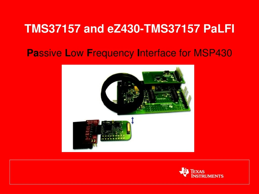
TMS37157 and eZ430 -TMS37157 PaLFI. Pa ssive L ow F requency I nterface for MSP430. TMS37157 PaLFI – Passive Low Frequency Interface Device. Basic Parts of TMS37157. TMS37157 (RFID Tag IC with user memory and SPI interface to Microcontroller) Inductor (pickup coil for TMS37157)

E N D
TMS37157 and eZ430-TMS37157 PaLFI Passive Low Frequency Interface for MSP430
TMS37157PaLFI – Passive Low Frequency Interface Device Basic Parts of TMS37157 • TMS37157 (RFID Tag IC with user memory and SPI interface to Microcontroller) • Inductor (pickup coil for TMS37157) • MSP430F2274 (or another suitable MSP430 with similar inputs (analog or digital) for desired sensors) • Sensor Measurement suggestions for applications : • Altitude, 3-Axis accelerometer, Pressure, etc. • Temperature (onboard MSP430)
TMS37157PaLFI – Passive Low Frequency Interface Device Key Features • Battery-less accessible memory • Battery charge function (VL, Vanadium Pentoxide) • Ultra low power • Microcontroller powered by LF field • Multi purpose LF interface to a microcontroller • Stand alone LF-transponder with memory
TMS37157Benefits / Features Features LF Benefits • Battery check and charge function (VL, Vanadium Pentoxide) • 3-Wire SPI interface • Integrated passive LF interface • Ultra low power: 50nA standby, 70µA active • Half duplex LF communication at 134kHz • 8kbit/s uplink data rate • 121 Bytes user EEPROM • 32 Bit unique serial number • Supply voltage range: 2 – 3.6V • Highest noise immunity due to HDX • communication • 50% higher read range compared to • FDX systems • Ultra reliable EEPROM • µC access via LF interface Applications • Semi-active transponder • Ultra low power data logger memory • Wireless, battery-less sensor interface • Configuration interface (PLC, CD/DVD Player) • Stand alone LF-transponder with memory
TMS37157PaLFI – Passive Low Frequency Interface Device eZ430-PaLFI Target Board eZ430 Emulator Stick eZ430-TMS37157 • Development Kit Includes: • eZ430 Emulator Stick • eZ430 Battery Board • eZ430-PaLFI Target Board • USB RFID Reader with Antenna • USB cable • Power Supply Cable (for onboard Amp Circuit )
Data Sheet and Manual for PaLFI and MSP430F2274 Application Reports and example source code in C for all transponder functions SPI library for using the TMS37157 with an MSP430 Reader/writer base station protocol description Recommended application circuit for PaLFI with RF guideline TMS37157PaLFI – Passive Low Frequency Interface Device Collateral Click page for TMS37157 Data Sheet
TMS37157PaLFI – Passive Low Frequency Interface Device Highlighted Special Features MSP ACCESS: • Reader sends a “MSP Access Command” together with 6 byte of data • TMS37157 detects MSP Access command and wakes up uC by setting VBATI and BUSY • uC can detect an MSP access command through VBATI or BUSY signal, request the 6 byte of data from the TMS37157, process it and send 6 bytes to the TMS37157 • TMS37157 transmits the received 6 Bytes of data back via the LF interface • The carrier has to remain on during the complete process BATTERY CHARGE: • Reader sends a “Battery Charge Command” to the TMS37157 and leaves the carrier on • TMS37157 applies a voltage of about 3.4V to VBAT -> battery or a capacitor are charged 7
TMS37157 PaLFI System Technical Training Agenda • Hardware • TMS37157 (PaLFI IC) • ez430-TMS37157 (PaLFI + MSP430 Target Board) • TMS3705A1DRG4 (LF Reader/Writer IC) • RI-ACC-ADR2 (Base Station or Reader/Writer) • Command/Protocol Details • PC to/from GUI level • Hardware level (MSP430 to/from TMS3705A1DRG4) • Firmware Considerations
TMS37157PaLFI – Passive Low Frequency Interface Device TMS37157 Internal Block Diagram
TMS37157PaLFI – Passive Low Frequency Interface Device TMS37157 User Memory Map
TMS37157PaLFI – Passive Low Frequency Interface Device TMS37157 User Memory Map (cont.)
TMS37157PaLFI – Passive Low Frequency Interface Device 2.66mH Inductor (PaLFI Antenna Coil) ez430-TMS37157 Target Board (ID Device) TMS37157 MSP430F2274
16 Pin SOIC Package TMS3705A1DRG4Low Frequency Base Station/Reader IC • Key Features • 5V device • Automatic sleep mode (TXCT idle for 100 ms) • Transponder resonance frequency measurement • Internal Full Bridge antenna driver • Digital demodulator • Diagnosis function • Several operating modes • self adapting or fixed frequency charge-up • automatic or fixed demodulator threshold • asynchronous or synchronous data to µP • Reduced additional component count • PLL for internal clock generation • 2/4 MHz crystal or low cost ceramic resonator can be used
TMS3705A1DRG4Low Frequency Base Station/Reader IC TMS3705A1DRG4 Internal Block Diagram VDD SCI- Encoder Digital Demodulator Diagnosis Limiter Tag Resonant - Freq. Measurement A_TST SCIO Band Pass 10k Power-on reset Control Logic with Mode Control Register SFB Amplifier RF TXCT Vref SENSE D_TST Full Bridge PLL VDDA F_SEL Controlled ANT1 Pre- drivers Frequency Divider OSC2 ANT2 VSSA OSC1 VSS VSSB
TMS37157PaLFI – Passive Low Frequency Interface Device TMS3705A1DRG4 Application Circuit (Base Station/Reader)
TMS37157PaLFI – Passive Low Frequency Interface Device • Technical Training Module: • Base Station and PaLFI communication basics • Pulse Position Modulation format details • PaLFI response format details
Base Station/PaLFI Communication Basics • ez430-TMS37157 Base Station currently uses Pulse Position Modulation (PPM) scheme to interface over the air with the ez430-TMS37157 target board. (Downlink) • The transponder will respond back over the air using FSK, with the demodulated and digitized response indicated here using the relationship of the signals between the TXCT and SCIO pins. • In the response string, it should be noted that the bytes are handled a certain way in order to interpret them. • For example, they come in LSB first and need to have one’s complement performed on them in order to translate them correctly.
Base Station Communication Basics (PPM Low and High Bits) • Blue trace is TXCT line on the TMS3705A1DRG4 • Green trace is the actual Low Frequency field generated by the reader IC being amplitude modulated Low Bit High Bit
PaLFI Communication Basics (Demodulated and Digitized PaLFI Response Low and High Bits) • Logic 1 = TXCT going high while SCIO line high • Logic 0 = TXCT going high while SCIO line low • Example 0x5A byte below shows LSB first bit string of 101001012. When rotated (to become MSB first) it becomes 101001012, then one’s complement is performed on the binary string, yielding 010110102 or 0x5A16.
TMS37157PaLFI – Passive Low Frequency Interface Device • Technical Training Module: • General Read of Page 3 (Command 0x0C) • Reading Page 3 returns pages 1, 2 and 3, which are the tag 8 bit Password/Selective Address, 8 bit User ID, 8 bit Manufacturing ID and Unique 24 Bit Serial Number Fields. • A read either of the Pages 1 or 2 will also result in these data fields being returned but with different CRCs and BCCs because the Page Requests are different.
TMS37157PaLFI – Passive Low Frequency Interface Device • In order to send commands to the TMS37157 LF interface, the user sends a Write Address byte comprising a 2-bit Command field and a 6-bit Page field. The Command field, which is transmitted first, determines the function to be executed and whether the command comprises additional data bytes that must also be sent. The Page field specifies the target of the command. The table below shows which additional data bytes must be included with each command type. The elements for each command are sent from left to the right of this table.
Command Implementation PaLFI General Read of Page 3 (Command 0x0C) [Using the GUI] Example Command/Response Sequences General Read of Page 3 Command • 01060632080C000A3C • 010B007EFF010E0329040EC0A8CD
Command Implementation PaLFI General Read of Page 3 (Command 0x0C) Overall Sequence (LF Charge Burst, Modulated Command, Tag Response)
Command Implementation PaLFI General Read of Page 3 (Command 0x0C) (Zoom on End of LF Charge Burst, Modulated Command, Tag Response) 0C 7E FF 01 0E 03 29 04 0E C0 A8
Command Implementation PaLFI General Read of Page 3 (Zoom on End of the LF charge burst and General Read Command 0x0C) [00110000 (rotated) = 00001100 = 0x0C] LSB MSB 0 0 1 1 0 0 0 0
Command Implementation PaLFI Read Page 3 Tag Response Example [Password, User ID and Manufacturing ID] • 7E = Start Byte • FF = Page 1 (Password) • 01 = Page 2 (User Data) • 0E = Part of Page 3 (Manufacturer ID byte) 7E FF 0E 01
Command Implementation PaLFI Read Page 3 Tag Response Example (Serial # and Page Address) • 03 = Page 3 (Serial # LSB) • 29 = Page 3 • 04 = Page 3 (Serial # MSB) • 0E = Page 3 (Page Address) 03 29 04 0E
Command Implementation PaLFI Read Page 3 Tag Response Example (CRC) • C0 = CRC (LSB) • A8 = CRC (MSB) C0 A8 Note: The CRC is calculated (with this device) over the string: FF010E0329040E using reverse CCITT, with a start value of 0x3791 • BCC (0xCD) (not shown here, but in the GUI) is XOR result taken over the entire response string: 0B007EFF010E0329040EC0A8whichisminus the SOF byte seen in the GUI.
TMS37157PaLFI – Passive Low Frequency Interface Device • Technical Training Module: • Battery Charge Command is: • Used to power attached microcontroller (without using battery) • Used to charge an attached system battery • When a Battery Charge Command has been received the TMS37157 applies a voltage of about 3.4 V to VBAT. • The charge current depends mainly on the antenna of the LC Tank Circuit and the Field Strength of the Base Station. • The TMS37157 does not answer to a Battery Charge Command. • The LF Field has to remain on after transmitting the telegram. The telegram format corresponds to a Read Page 26 Command. • The charging of the battery can be ended by any other command.
TMS37157PaLFI – Passive Low Frequency Interface Device Command Implementation Battery Charge command (Page26, 68h)
Command Implementation Battery Charge Command (0x68) [Using the GUI] Example Command/Response Sequences Battery Charge Command • 01078610190868000AE2 • 01078610190868000AE230383638
Command Implementation Battery Charge command (Overall Sequence)
LSB MSB 0 0 0 1 0 1 1 0 Command Implementation Battery Charge (Command 0x68, using PPM)
TMS37157PaLFI – Passive Low Frequency Interface Device • Technical Training Module: • Microcontroller Access/Program Command (with and without a battery or other DC power source) • The MSP Access command allows transfer of LF data to/from a microcontroller (i.e. MSP430) via the TMS37157 Analog Front End. • The microcontroller handles data transfers using the following SPI commands: • MSP Read Data From PCU (Data In) • MSP Write Data To PCU (Data Out)
TMS37157PaLFI – Passive Low Frequency Interface Device • MSP Access Data Handling Flow: The following sequence is needed to implement an MSP Access command: • The TMS37157 detects that an MSP Access command has been received and wakes the Microcontroller (e.g. MSP430). • The Microcontroller reads the status using the SPI command Get Status. • The MSP access request is detected and the data are requested by the Microcontroller. Data bytes are transferred to the Microcontroller using the SPI command MSP Read Data from PCU. • The data bytes are processed and actions executed, as necessary. • If necessary, the Microcontroller sends response data bytes back to the TMS37157, using the SPI command MSP Write Data to PCU. • After the TMS37157 has detected removal of LF power, the response data bytes are sent back to the base station (i.e. TMS3705A1DRG4 based reader). NOTE: • The LF field must be present throughout the above sequence (except the last step), otherwise a malfunction of the TMS37157 may occur.
TMS37157PaLFI – Passive Low Frequency Interface Device Command Implementation MSP Access/Program command with a Battery (Page31, 7Dh) MSP430
Command Implementation MSP430 Access/Program Command Flash Green LED 4 Times with a Battery [Using the GUI] Example Command/Response Sequences (happening behind the scenes) MSP430 Access Command • 010E0632487D040000000000AF58050AF3 • 010B007E0400000000007D14B0A8 MSP430 Access Command (for Red LED) • 010E0632487D040100000000EB53050ABD • 010B007E0401000000007D3FB486
Command Implementation MSP430 Program/Access Command DEADBEEF1234 with a Battery [Using the GUI] Example Command/Response Sequences MSP430 Access Command • 010E0632487D3412EFBEADDEE9810F0A66 • 010B007E3412EFBEADDE7DFF9764
Command Implementation MSP430 Access/Program Command with a Battery [Overall]
Command Implementation MSP430 Access/Program Modulated Commands Flash Green LED 4 times and DEADBEEF1234 with a Battery [Overall] 7D 04 00 00 00 00 00 AF 58 7D 34 12 EF BE AD DE E9 81 Modulated Command for flashing Green LED 4 times Modulated Command for sending DEADBEEF1234
Command Implementation MSP430 Access/Program TMS37157 Responses Flash Green LED 4 times and DEADBEEF1234 with a Battery [Overall] 7D 04 00 00 00 00 00 7D 14 B0 7E 34 12 EF BE AD DE 7D FF 97 MSP430 thru TMS37157 response from flashing Green LED 4 times (with CRC) MSP430 thru TMS37157 response from sending DEADBEEF1234 (with CRC)
TMS37157PaLFI – Passive Low Frequency Interface Device Command Implementation MSP Access/Program command without a Battery (Page31, 7Dh) MSP430
Command Implementation MSP430 Access/Program Command Flash LED 4 Times without a Battery [Using the GUI] Example Command/Response Sequences (happening behind the scenes) Read Page 3 Command 01060632080C000A3C • 010B007EFF010E0329040EC0A8CD Battery Charge Command • 01078610190868000AE2 • 01078610190868000AE230383638 MSP430 Access Command • 010E0632487D040000000000AF58050AF3 • 010B007E0400000000007D14B0A8 Battery Charge Command • 01078610190868000AE2 • 01078610190868000AE230383638 Read Page 3 Command • 01060632080C000A3C 010B007EFF010E0329040EC0A8CD
Command Implementation Overall MSP430 Access Command without Battery (Program MSP430 and Flash LED four times example) • This is a combination of the previous commands described in this training module. • Read Page 3, Battery Charge and MSP Access
TMS37157PaLFI – Passive Low Frequency Interface Device • Technical Training Module: • Firmware Considerations • Read Page 3 • Battery Charge • MSP Access
TMS37157PaLFI – Passive Low Frequency Interface Device • Read Page 3 • The Transponder Memory comprises a total of 126 bytes, organized in pages. • Memory space is apportioned as follows: • User Data 121 bytes • Serial Number (3 bytes) + Manufacturer ID (1 byte) = 4 bytes • Selective Address 1 byte • A read of Page 3 returns three pages of data • Page 1 = Password • Page 2 = User Data 1 • Page 3 = Serial Number and Manufacturer ID
Read Page Command Firmware Code Snippet void SPI_Read_SerialNum(void) /**************************************************************************************** * Read out Serial Number, MID, User Data 1 and Password (Pages 1, 2 and 3) ****************************************************************************************/ { SPI_Set_Up_Telegram(); SPI_Buf_Set_Output_Byte(Page3); SPI_Buf_Set_Telegram_Length(); SPI_Buf_Send(); if (MSP430_SPI_Rx(SPI_Stack.ucInput,7)) ErrorMode(); TRP_Data.SelectiveAddress = SPI_Stack.ucInput[0]; TRP_Data.KeyNumber = SPI_Stack.ucInput[1]; // equal to User data 1 TRP_Data.SerialNumber[0] = SPI_Stack.ucInput[2];// Manu Code / Page 3 TRP_Data.SerialNumber[1] = SPI_Stack.ucInput[3];// Ser. Nr. / Page 3 TRP_Data.SerialNumber[2] = SPI_Stack.ucInput[4];// Ser. Nr. / Page 3 TRP_Data.SerialNumber[3] = SPI_Stack.ucInput[5];// Ser. Nr. / Page 3 }
TMS37157PaLFI – Passive Low Frequency Interface Device • Battery Charge • When a Battery Charge Command has been received the TMS37157 applies a voltage of about 3.4 V to VBAT. • The charge current depends mainly on the antenna of the LC Tank Circuit and the Field Strength of the Base Station. • The TMS37157 does not answer to a Battery Charge Command. • The LF Field has to remain on after transmitting the telegram. The telegram format corresponds to a Read Page 26 Command. • The charging of the battery can be ended by any other command. • The write data format of the Battery Charge Command is shown below
TMS37157PaLFI – Passive Low Frequency Interface Device • MSP Access • The MSP Access Commands are special cases; they work only if the TMS37157 receives an MSP Access Command through its RF Interface. • The MSP Access Commands are used to transfer data through the RF Interface directly to the MSP and back. • In the normal application the MSP is in LPM4 waiting for an Interrupt and the TMS37157 is in Standby mode, resulting in overall ultra low power consumption. • If the TMS37157 receives an MSP Access Command, it sets Busy high. This can be used as an Interrupt for the MSP430. • The TMS37157 shows its readiness by resetting busy. Now the MSP can request the data from the TMS37157. • The TMS37157 waits until the MSP send 6 Bytes of data back to the TMS37157. • During this time, the field of the RFID reader has to stay on, supplying the TMS37157 with Energy. • The TMS37157 sends the Data back to the RFID reader, when the RFID reader switches off the field. • The following code snippet shows how to use the MSP Access Commands in connection with a Busy Interrupt. • It is assumed that Busy Pin is connected to P2.1 of the MSP.
MSP Access Command Firmware Code Snippet #include "msp430x22x4.h" #include "PaLFI_Transponder.h" void main (void) { unsigned char MSP_Access_Data[6] = {0}; P2OUT = 0; // P2DIR &= ~CU_BUSY; // Busy Input P2.1 CU_BUSY = 0x002 P2IFG &= ~CU_BUSY; // reset busy Interrupt P2IE |= CU_BUSY; // busy Interrupt enabled While(1) { if((P2IFG & CU_BUSY) == CU_BUSY)); // Test for Interrupt { While ((P2IN & CU_BUSY) == CU_BUSY); // wait until TMS37157 ready SPI_Read_CU_Data(MSP_Access_Data); // read Data from TMS37157 MSP_Access_Data[1] = MSP_Access_Data[2] + MSP_Access_Data[3]; // change data SPI_Write_CU_Data(MSP_Access_Data); // Write Data to TMS37157 P2IFG &= ~CU_BUSY; // reset Interrupt Flag P2IE |= CU_BUSY; // set Interrupt enabled } __bis_SR_register(LPM4_bits + GIE); // Enter LPM4, global Interrupts Enabled } } #pragma vector=PORT2_VECTOR __interrupt void PORT2_ISR(void) { P2IE &= ~CU_BUSY; __bic_SR_register_on_exit(LPM4_bits+GIE); }