Download
1 / 39
530 likes | 964 Vues
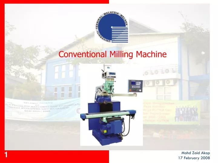
Conventional Milling Machine. Mohd Zaid Akop 17 February 2008. FAKULTI KEJURUTERAAN MEKANIKAL UNIVERSITI TEKNIKAL MALAYSIA MELAKA. CONTENTS. Introduction Machine Component Milling Cutters Milling Operation Milling Parameter.

E N D
Conventional Milling Machine Mohd Zaid Akop 17 February 2008
FAKULTI KEJURUTERAAN MEKANIKALUNIVERSITI TEKNIKAL MALAYSIA MELAKA CONTENTS Introduction Machine Component Milling Cutters Milling Operation Milling Parameter
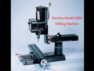
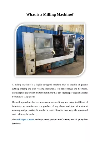
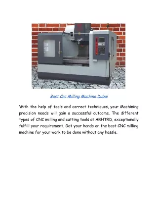
FAKULTI KEJURUTERAAN MEKANIKALUNIVERSITI TEKNIKAL MALAYSIA MELAKA 1. INTRODUCTION • Introduction to Milling Process • Milling is the method of machining by cutting in which the tool carries out a rotary motion while the work piece is fixed on a movable table. • Milling is a machining process used to produced various shape of products / parts except round. • Milling machines are used to: • Machine plain and rough surface • Make a tapping and gearing • Drilling • Boring • Slotting • Divided into two (2) types • Vertical milling machine • Horizontal milling machine
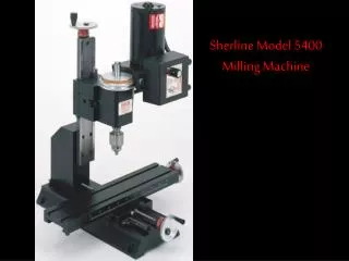
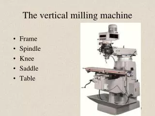
FAKULTI KEJURUTERAAN MEKANIKALUNIVERSITI TEKNIKAL MALAYSIA MELAKA 1. INTRODUCTION-(cont’d) • Vertical milling machines are the most commonly used machine in tool and die maintenance and job shop • Some machines have milling head that can be tilted • Can produce horizontal surface, Vertical surfaces, angular surface, Shoulders, grooves, fillet, keyways, T slot and dovetails Vertical Milling Machine
FAKULTI KEJURUTERAAN MEKANIKALUNIVERSITI TEKNIKAL MALAYSIA MELAKA 1. INTRODUCTION-(cont’d) Horizontal Milling Machine
FAKULTI KEJURUTERAAN MEKANIKALUNIVERSITI TEKNIKAL MALAYSIA MELAKA 2. MACHINE COMPONENT • Vertical Milling Machine • The major assemblies of a vertical milling machines are: • Base and Column • Knee • Saddle • Table • Ram • Toolhead Vertical Milling Machine (R.R.Kibbe, 2006)
FAKULTI KEJURUTERAAN MEKANIKALUNIVERSITI TEKNIKAL MALAYSIA MELAKA 2. MACHINE COMPONENT-(c’d) • Vertical Milling Machine: Components and Functions • Base & column are one piece, and are the major structural components. • Knee supports the saddle and table. It can moves up and down. • Vertical traverse crank controls the knee up and down movement. • Saddle supports the table. It can moves in and out. • Cross traverse handle controls the saddle in and out movement. • Workpiece or work-holding device is secured to the table. It can moves right and left. • Table traverse handle controls the table right and left movement. • Ram engages the swiveling slide on top of the column. It moves in and out by turning the ram positioning pinion gear. • Toolhead is attached to the end of ram and contains motor, which powers the spindle. • Quill is nonrotating and contains rotating spindle. It can be extended or retracted into the tool head by adjusting the quill feed hand lever or handwheel.
FAKULTI KEJURUTERAAN MEKANIKALUNIVERSITI TEKNIKAL MALAYSIA MELAKA 2. MACHINE COMPONENT-(c’d) • Horizontal Milling Machine • The major assemblies of a horizontal milling machines are: • Base and Column • Knee • Saddle • Table • Spindle • Overarm and Arbor Support Similar to Vertical Milling Machine Horizontal Milling Machine (R.R.Kibbe, 2006)
FAKULTI KEJURUTERAAN MEKANIKALUNIVERSITI TEKNIKAL MALAYSIA MELAKA 2. MACHINE COMPONENT-(c’d) • Horizontal Milling Machine: • Spindle is located at in the upper part of the column. It is used to hold, align, and drive the various cutters, chucks, and arbors. • Overarm engages the slide on the top of the column and can be moved in and out by loosening the overarm clamps. • Arbor support contains a bearing that is exactly in line with the spindle.
FAKULTI KEJURUTERAAN MEKANIKALUNIVERSITI TEKNIKAL MALAYSIA MELAKA 3. MILLING CUTTERS • Milling Cutters • Characteristic of milling cutters • Must be tougher than workpiece that is going to be machined. • Able to withstand high pressure during cutting. • Able to withstand high temperature. • Must have high wear resistance. • Most of the milling cutters are made of ‘high speed steel’ or tungsten carbide. • It is consist of ferrum, carbon, molebdenum, vanadium and cromium. • carbon – harder agent • tungsten & molebdenum – to maintain the hardness at high temperature • vanadium – to increase the toughness • cromium – to increase the hardness and resistant to worn out • Tungsten carbide – used for harder workpiece. Long last but higher cost
FAKULTI KEJURUTERAAN MEKANIKALUNIVERSITI TEKNIKAL MALAYSIA MELAKA 3. MILLING CUTTERS-(cont’d) • Cutters for Vertical Milling Machine i) Face Milling Cutter • Used to machine the surface of workpiece. • Consist of several insert teeth attached to cutter wheel. • Insert teeth are using high speed steel or tungsten carbide. Face Milling Cutter
FAKULTI KEJURUTERAAN MEKANIKALUNIVERSITI TEKNIKAL MALAYSIA MELAKA 3. MILLING CUTTERS-(cont’d) • ii) End Mills Cutter • Used to machine slot and certain shape. • Consist of cutting teeth from end to the top. Ball Nose Cutter End Milling Cutter • iii) Ball Nose Cutter • Used to machine slot and concave shape. • Same as end mill cutter except round shape at their end.
FAKULTI KEJURUTERAAN MEKANIKALUNIVERSITI TEKNIKAL MALAYSIA MELAKA 3. MILLING CUTTERS-(cont’d) iv) T-slot cutter Used to machine T-slot after using end mill cutter. T-slot Cutter Keyseat Cutter v) Keyseat cutter Used to machine slot to match with ‘standard woodrooff keys’ at shaft.
FAKULTI KEJURUTERAAN MEKANIKALUNIVERSITI TEKNIKAL MALAYSIA MELAKA 3. MILLING CUTTERS-(cont’d)
FAKULTI KEJURUTERAAN MEKANIKALUNIVERSITI TEKNIKAL MALAYSIA MELAKA 3. MILLING CUTTERS-(cont’d)
FAKULTI KEJURUTERAAN MEKANIKALUNIVERSITI TEKNIKAL MALAYSIA MELAKA 3. MILLING CUTTERS-(cont’d)
FAKULTI KEJURUTERAAN MEKANIKALUNIVERSITI TEKNIKAL MALAYSIA MELAKA 3. MILLING CUTTERS-(cont’d) • Cutters for horizontal milling machine • i) Plain milling cutters • Cylinder shape with cutting teeth at the outside. • Cutting teeth < 19mm width, straight shape & suitable for machining slot and plain surface. • Cutting teeth > 19mm width, spiral shape & suitable for machining rough surface. Plain Milling Cutter
FAKULTI KEJURUTERAAN MEKANIKALUNIVERSITI TEKNIKAL MALAYSIA MELAKA 3. MILLING CUTTERS-(cont’d) • ii) Angular cutters • Their teeth is not parallel or not 90 degree with cutting axis. • Used for grinding surface or machining with angle. Angular Cutter
FAKULTI KEJURUTERAAN MEKANIKALUNIVERSITI TEKNIKAL MALAYSIA MELAKA 3. MILLING CUTTERS-(cont’d) • iii) Form cutters • Used to machine certain shape, same as the cutter shape. • Eg: convex and concave surface Form Cutter
FAKULTI KEJURUTERAAN MEKANIKALUNIVERSITI TEKNIKAL MALAYSIA MELAKA 3. MILLING CUTTERS-(cont’d) • iv) Metal slitting saw • Used to machine ‘deep’ slot or cutting length of the workpiece. • Size of the cutter is smaller at center than outside to make a clearance between cutter and workpiece. Metal Slitting Cutter
FAKULTI KEJURUTERAAN MEKANIKALUNIVERSITI TEKNIKAL MALAYSIA MELAKA 4. MILLING OPERATION • Cutting Direction • Based on the direction of movement of the milling cutter and the feeding direction of workpiece. • There are two types (horizontal milling machine) • Up milling • Down milling • i) Up milling • Cutting tool rotates in the opposite direction to the table movement. • The chip start at zero thickness and gradually increases to the maximum. • Also known as conventional milling Up Milling
FAKULTI KEJURUTERAAN MEKANIKALUNIVERSITI TEKNIKAL MALAYSIA MELAKA 4. MILLING OPERATION-(cont’d) • Advantages: • No backlash-(normal wear between table screw and the nut in which it turn) • Suitable for casting or hot rolled steel. • Lower milling force • Disadvantages: • Length of chips is longer than down milling, more engagement of tool and w/p, reduce tool life. • Force tends to lift the workpiece from the table, needs good fixturing. • Lower cutter life. • Rough Surface / machine mark –creating rubbing and burnishing effect with excessive friction, high temperature.
FAKULTI KEJURUTERAAN MEKANIKALUNIVERSITI TEKNIKAL MALAYSIA MELAKA 4. MILLING OPERATION-(cont’d) • ii) Down milling • Cutting tool rotates in the same direction to the table movement. • The chip start at maximum thickness and gradually decreases to the zero thickness • Most preferred technique. • Also known as climb milling or in cut milling Down Milling
FAKULTI KEJURUTERAAN MEKANIKALUNIVERSITI TEKNIKAL MALAYSIA MELAKA 4. MILLING OPERATION-(cont’d) • Advantages: • Eliminating the feed marks and obtain better surface finish. • Suitable to machine thin and hard to hold parts since the workpiece is forced against the table. • Consistent parrallelism and size can be maintained particularly on thin parts. • It can be used where breakouts at the edge of workpiece cannot be tolerated. • Length of chip is less than up milling-less engagement of tool and w/p (less force to unit volume of material removed). Up to 20% less power. • Longer cutter life. • Disadvantages: • Possibility that backlash present in the table. • Cannot be used unless the machine has backlash eliminator and the table jigs have been tightened. • Cannot be used for machining casting or hot rolled steel, since the harder outer scale will damage the cutter
FAKULTI KEJURUTERAAN MEKANIKALUNIVERSITI TEKNIKAL MALAYSIA MELAKA 4. MILLING OPERATION-(cont’d) • Typical Milling Operations • There are several types of milling operation depends on types of milling machine and cutting tools provided. Plain Milling • Plain milling is the milling of a flat surface with the axis of the cutter parallel to the machining surface. It can be carried out either on a horizontal machine or a vertical machine as shown below. Plain Milling
FAKULTI KEJURUTERAAN MEKANIKALUNIVERSITI TEKNIKAL MALAYSIA MELAKA 4. MILLING OPERATION-(cont’d) • End Milling • End Milling is the milling of a flat surface with the axis of the cutter perpendicular to the machining surface as shown below. • End milling is used to produce features like steps, squaring, milling a cavity or pocketing, and slot cutting. • Clip mill_slot End Milling
FAKULTI KEJURUTERAAN MEKANIKALUNIVERSITI TEKNIKAL MALAYSIA MELAKA 4. MILLING OPERATION-(cont’d) • Gang Milling • Gang milling is a horizontal milling operation that utilises three or more milling cutters grouped together for the milling of a complex surface in one pass. • As illustrated in below figure, different type and size of cutters should be selected for achieving the desire profile on the workpiece. Gang Milling
FAKULTI KEJURUTERAAN MEKANIKALUNIVERSITI TEKNIKAL MALAYSIA MELAKA 4. MILLING OPERATION-(cont’d) • Straddle Milling • In straddle milling, a group of spacers is mounted in between two side and face milling cutters on the spindle arbor as shown below. Used for the milling of two surfaces parallel to each other at a given distance. • Work Holding • A variety of work holding devices can be used for holding the workpiece depending upon the types of workpice and types of milling to be done. • For example: vice, universal chuck, fixture and clamp. Straddle Milling
FAKULTI KEJURUTERAAN MEKANIKALUNIVERSITI TEKNIKAL MALAYSIA MELAKA 4. MILLING OPERATION-(cont’d) • i) Vice • The most common device. • Used for holding small and regular workpieces. • The vice is mounted on the table using T-slots. Vice Jaw
FAKULTI KEJURUTERAAN MEKANIKALUNIVERSITI TEKNIKAL MALAYSIA MELAKA 4. MILLING OPERATION-(cont’d) • ii) Universal chuck • Used for holding round workpieces for machining of end slots, splines, etc. • iii) Fixture • The most common form of work holding device used in ‘production milling’ operation. • Used to reduce the set-up time and increase the locational accuracy and repeatability. • Clip mill_holddn Fixture 1
FAKULTI KEJURUTERAAN MEKANIKALUNIVERSITI TEKNIKAL MALAYSIA MELAKA 4. MILLING OPERATION-(cont’d) Fixture 2
FAKULTI KEJURUTERAAN MEKANIKALUNIVERSITI TEKNIKAL MALAYSIA MELAKA 5. MILLING PARAMETER • Milling Parameter • i) Cutting speed • It is important to control the cutting speed because high-speed may results in excessive cutter’s worn out but if too slow, it will increase the cutting time. • Cutting speed measured in meter per minutes (m/min). • It is varies for different metals due to the hardness, microstructure and machinability. • Table below shows example of cutting speed for various types of the material.
FAKULTI KEJURUTERAAN MEKANIKALUNIVERSITI TEKNIKAL MALAYSIA MELAKA 5. MILLING PARAMETER-(cont’d) Data for Milling
FAKULTI KEJURUTERAAN MEKANIKALUNIVERSITI TEKNIKAL MALAYSIA MELAKA 5. MILLING PARAMETER-(cont’d) Cutter Speed • Cutter speed is measured in rotation per minute (rpm). • It is depends on : • Types of work pieces • Cutter materials • Cutter diameter • Required surface finish • Toughness of the machine • In mathematically, cutter speed, N : • N = 1000 x V N = cutter speed (rpm) • π x D V = cutting speed (m/min) • D = cutter diameter (mm)
FAKULTI KEJURUTERAAN MEKANIKALUNIVERSITI TEKNIKAL MALAYSIA MELAKA 5. MILLING PARAMETER-(cont’d) Feeding rate • Rate of feeding work pieces to the machine cutter. • Feeding rate is measured in millimeter per minute (mm/min). • It is depends on: • Cutting depth and width • Work piece materials • Types of cutters • Sharpness of cutters • Required accuracy In mathematically, feeding rate, v: v = fNn v = feeding rate (mm/min) f = feed / tooth (mm/rotation) N = cutting speed (rpm) n = number of teeth
FAKULTI KEJURUTERAAN MEKANIKALUNIVERSITI TEKNIKAL MALAYSIA MELAKA 5. MILLING PARAMETER-(cont’d) • Cutting Depth • Depth of metal cutting will affects the surface roughness and cutter life. • For guidelines (table for metal trade -Serope Kalpakjian) • a 5.0 mm for roughness • a 0.5 mm for finishing • It is normal practice to reduce the cutting speed when increase the cutting depth to avoid machine cutter from broken.
FAKULTI KEJURUTERAAN MEKANIKALUNIVERSITI TEKNIKAL MALAYSIA MELAKA 5. MILLING PARAMETER-(cont’d) Example: A surface 115 mm wide and 250 mm long is to be rough milled with a depth of cut 2 mm by a 5-tooth tungsten carbide face mill 70 mm in diameter. If the work material is stainless steel with cutting speed 85 m/min and feed rate of cutter is 0.13 mm /tooth, calculate: a) Cutter speed b) Feeding rate of the work piece 37
FAKULTI KEJURUTERAAN MEKANIKALUNIVERSITI TEKNIKAL MALAYSIA MELAKA 5. MILLING PARAMETER-(cont’d) Answer a) Cutter speed, N = 1000 x V π x D = 1000 x 85 3.14 x 70 = 387 rpm b) Feeding rate, v = fNn = 0.13 x 387 x 5 = 251 mm/min
FAKULTI KEJURUTERAAN MEKANIKALUNIVERSITI TEKNIKAL MALAYSIA MELAKA THE END THANK YOU