Download
1 / 35
350 likes | 524 Vues
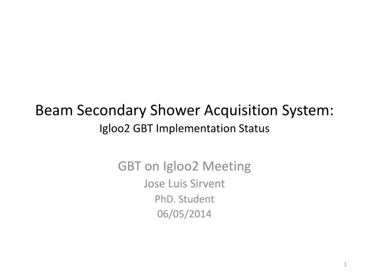
Beam Secondary Shower Acquisition System: Igloo2 GBT Implementation Status. GBT on Igloo2 Meeting Jose Luis Sirvent PhD. Student 06/05/2014. 0. Introduction 1.1 Wire Scanner principle. Invasive method for beam transverse profile measurement.

E N D
Beam Secondary Shower Acquisition System:Igloo2 GBT Implementation Status GBT on Igloo2 Meeting Jose Luis Sirvent PhD. Student 06/05/2014
0. Introduction1.1 Wire Scanner principle • Invasive method for beam transverse profile measurement. • Carbon wire interaction (30um) generates shower of secondary particles. • Transversal profile: • Wire position (X axis) • Secondary rain (Y axis) • System compromises: • Wire blow-up (heat) • Losses produced • Mechanical stresses (Bellows) • Calibration procedures • Vibrations • Types: • Rotating Fast • Rotating Short/Long • Linear • Total Scanners: 31 • Usage in a daily basis at CERN
0. Introduction1.2 BWS Prototype (Mechanical Aspects) • Scan at least as fast as the existing system (20 m/s needed to avoid wire damage) • Absolute accuracy of beam width determination of about 5 um (~5%) • Reduction of play in mechanical system • All elements mounted on same axis • High accuracy angular position sensor • Optical position sensor (Encoder) • Overcome bellow limitations • Locate all moveable parts in the vacuum • Minimize fork and wire deformations: • Acceleration profile optimized for low vibrations • Mechanical design for minimum shaft and forks deformation • Unified design for integration in the different accelerators (PS, SPS & LHC) X Axis: Optical position sensor Resolver Y Axis: Diamond Detector Magnetic Stopper Stepped Vacuum Barrel Motor Carbon Wire
0. Introduction1.3 Complete test assembly for Proof of concept evaluation Power QIE10 Test Board Needed to be developed Coax Cable 50 ohm (1-10m) QIE10 A SMA Connector Passive Splitting System Monitoring PC QIE10 B SMA pCVD Cividec Module VFC Board Or Arria V Dev. Kit RF Resistive network Igloo2 Development board with GBTx firmware emulation Motivation: The final proof-of-concept can be evaluated by using this assembly. The Igloo2 in this case could be configured to act purely as a GBTxasic, this way the system could be suitable to work with Igloo2 or GBTx in case of change for final board. Tasks: The system has to be configured to work in a complete assembly by using the knowledge from the previous tasks. The set-up should be done in a way to make possible Igloo2-> GBTx migration. Final tests and evaluation has to be done in with the assembly for system demonstration At this point a decision could be done regarding the FPGA usage or the development of a compact board with GBTx.
0. Introduction1.4 Development of a compact board for BWS pCVD diamond detector readout TTC NEW VFC VME FMC Carrier Board BOBR VME Board SFP+ Ethernet SFP+ FMC Connector FPGA Arria V Clk_bunch Clk_Turn Clk_Events Back plane VME64 Connector Back plane VME64 Connector Power VTRx SFP+ Passive Splitting System QIE10 A SFP+ SMA Fibre Optic TTC Data Control Memory Memory Igloo2 Or GBTx pCVD SFP+ QIE10 B SMA SFP+ Cividec Module VME FMC Carrier Board (VFC) Back-End VME Crate Compact Front-End Board Needed to be developed RF Resistive network Motivation: Finally the last part of the project would be the development and testing of a very simple and compact board containing the Rad-Hard or Rad-Tol components. Tasks: The QIE10 development board previously done has to be extended house the FPGA (or GBTx) and VTRx in the same board. Extensive testing has to be done in this board to guarantee that the performance reached in the development kits is repeated in this version. Radiation studies are also important to characterize the complete radiation hardness of the board and identify failures. This system could be installed in paralel with an operational BWS PMT & Scintillator system to crossvalidate performances.
1.GBT-FPGASome information and resources GBT-Protocol implementation on FPGAS for GBTx communication & Emulation: • Public SharePoint: https://espace.cern.ch/GBT-Project/GBT-FPGA/default.aspx • Public SVN Releases (old): https://svnweb.cern.ch/cern/wsvn/gbt_fpga • Mailing List: gbt-fpga-users@cern.ch • Contacts for support: sophie.baron@cern.ch , manoel.barros.marin@cern.ch Last news: • PH-ESE Repository (last updates): https://svn.cern.ch/reps/ph-ese/be/gbt_fpga • Indico Follow-up (GBT-FPGA): https://indico.cern.ch/event/283075/ • Support & code available for (Dev. Kits): • Xilinx Virtex 5 / 6 / 7 & Kinex 7 … • Altera Cyclone V & Statrix V… • Microsemi: Smatrfusion2, Igloo2 ??? At least not yet… but makes sense (CMS, MOPOS, us…) Two Versions: Standard (STD) Data Readout (DAQ) Low and Deterministic latency (LATOP) FE control & Time, Trigger and control (TTC) First Release 2011 First Release March 2014
1.GBT-FPGAThe Basic concept (Modular design) GBT-FPGA Firmware Starter Kit for Altera and Xilinx devices. Sophie Baron 2010. CERN/PH/ESE. GBT-FPTA Starter kit user guide V0.1 * Vendor Specific Modules (IP Cores)
1.GBT-FPGAThe Basic concept (Clocking Scheme and TTC clock recovery) GBT-FPGA Comments on deterministic latency and recommendations to handle optimization schemes. Sophie Baron, PH/ESE. 2011
1.GBT-FPGACurrent Status (Latency optimization) GBT-FPGA One unified core for multiple users. Manoel Barros Marin, PH/ESE/BE Students-Fellows seminar (05/02/2014).
2. Igloo2 GBT-FPGAThe code and the work I’m carrying out • For the moment I’ll migrate with the old STD version and only GBT frame (simplest), once done, tested and well understood, I’ll move to LATOP version.
2. Igloo2 GBT-FPGA STD: Implementation statusSubstitute Xilinx IP’s by Microsemi IP’s (Some are straighforward)
2. Igloo2 GBT-FPGA STD: Implementation statusSubstitute Xilinx IP’s by Microsemi IP’s (Others.. not) • Transceiver with EPCS @ 4.8GBPS: • - A lot of configuration registers • - Big amount of documentation • - Different implemented protocols (not needed) • - Power-Up Initialization needed (HPMS) • - Synchronization issues • - Needed standalone testing and verification
3. GBT-FPGA Overview in Igloo2:(Clock Management as in Virtex 6) GBT_BANK (Very simplified view) SERDES_INIT_MASTER APB_BUS (PLL) Data_In (83 bits) @40Mhz Tx_Word (19 bits) @ 240MHz Tx_CLK (240MHz) GBT_TX Scrambler Encoder Gearbox GBT_MGT SERDES_0 Vendor Specific IP TX_Data_P (4.8Gbps) TX_Data_N (4.8Gbps) TX_Word_CLK (240MHz) TX_Frame_CLK (40MHz) RefCLK1_P (120MHz) RefCLK1_N (120MHz) Rx_CLK (240MHz) RX_Data_P (4.8Gbps) RX_Data_N (4.8Gbps) Rx_Word (19 bits) @ 240 MHz Data_Out (83 bits) @ 40Mhz GBT_RX Gearbox Decoder Descrambler RX_Word_CLK (240MHz) RX_Frame_CLK (40MHz) RX_PLL TX_PLL
3. GBT-FPGA Overview in Igloo2:3.1 The MGT block (Schematic view) Written from scratch • According to Documentation: • When using SERDES the HPMS should drive the APB bus for Configuration. • 1 PLL Needed • No full control over SERDES • Manual configuration is possible • SERDES Registers should be properly initialized when using EPCS • When using EPCS the SERDES should be in PMA driven mode (manual bit lock steps). • Microsemi Recommends Default configurations with minor changes: • 1.25 / 2.5 GBPS • Lack of documentation for custom modes • Libero is constantly being updated and bugs repared…
3. GBT-FPGA Overview in Igloo2:3.1 The MGT block (Schematic view) Written from scratch • Recommendations by Microsemi: • Shadow_FIFOs with CLKint • Clock Constrains in TX & RX CLKs • Place FIFOS as close as possible from SERDES • Drive the 4 lanes reset with the same signal!! • Otherwise does not work!! APB_BUS CLK_TX_WORD CLK_RX_WORD
3. GBT-FPGA Overview in Igloo2:3.1 The MGT block : SERDES Initialization & Control • Done through the Igloo2_APB_MASTER: • Access to the SERDES registers for configuration and status check. Decides which actions to execute, registers to configure and work-flow Interface with the APB Bus protocol Very simple Read_Write Operations
3. GBT-FPGA Overview in Igloo2:3.1 The MGT block : SERDES Initialization & Control • Taking a look at Igloo2_SERDES_APB_MANAGER: Registers Initialization SERDES_CLK = REF_CLK1 EPCS Mode @ 4.8Gbps PMA Driven Mode (Manual bit lock) F = 2 M = 1 N = 20 Lanes Impedance 50ohm IDLE RESET Register = Register + 1 Initialization All Registers initialized Init_Done RX_RESET Refresh Serdes Status RX_RESET Refresh_Status READ SERDES_TEST_OUT CDR_FREQ_LOCK Update Outputs CDR_PHASE_COARSE Maintaining its setup time CDR_PHASE_FINE
3. GBT-FPGA Overview in Igloo2:3.1 The MGT block : SERDES Initialization & Control • Taking a look at Igloo2_SERDES_APB_MANAGER: Registers Initialization SERDES_CLK = REF_CLK1 EPCS Mode @ 4.8Gbps PMA Driven Mode (Manual bit lock) F = 2 M = 1 N = 20 Lanes Impedance 50ohm IDLE RESET Register = Register + 1 Initialization • Caution: • I need to continue working here!! • For the moment the SERDES doesn’t lock to the bit Stream • Initialization sequence, RX_Reset operation? All Registers initialized Init_Done RX_RESET Refresh Serdes Status RX_RESET Refresh_Status READ SERDES_TEST_OUT CDR_FREQ_LOCK Update Outputs CDR_PHASE_COARSE Maintaining its setup time CDR_PHASE_FINE
3. GBT-FPGA Overview in Igloo2:3.2 The GBT_TX & GBT_RX modifications done: • Changed the Xilinx IP by the Microsemi’s: • Core: Two-Port Large SRAM • Adapt code for ports names in: • TX: gbt_tx_gearbox_std_dpram.vhdl • RX: gbt_rx_gearbox_std_dpram.vhdl Igloo2_txdpram_core Igloo2_rxdpram_core
3. GBT-FPGA Overview in Igloo2:3.3 Surrounding Infrastructure: • From GBT-FPGA examples • Pattern Generator: Generates Fixed or counts • GBT Bank Reset manager: Resets all in order • Error Detector: To check transmission • Pattern Match: For delay determination • From me • SERDES_INIT_REGISTERS • PLLs for 240 to 40Mhz: Word to Frame CLK • UART communication: • For debugging on the PC • Check transmission status • Perform modules control : • Resets, Pattern, Serdes Lane… • From GBT_Bank: • Configuration files • gbt_bank_package • gbt_bank_user_setup • vendor_specific_gbt_bank_package
3. GBT-FPGA Overview in Igloo2:3.4 Communication with PC: Through Igloo2 UART Core Microsemi Provides Drivers for PC to emulate Serial port through USB: Makes life easier when accessing to the USB when programming an application. Microsemi Provides Core for FPGA to communicate with the UART (the board has a UART to USB interface) Only needed to develop a “translator” module that interfaces the CORE with the Fabric signals you are interested to control
4.Tests done so far in Igloo2: 4.1 Testing GBT_TX & GBT_RX modified modules • It was needed to verify that the TX & RX modules work well with the modifications done. • Dual Port Rams Xilinx IPs substituted by MicrosemiIps (GBT-FPGA STD Version) • Design unconstrained up to now. (Improvements are specked) 84 Bits @ 40MHz 20 Bits @ 240MHz 84 Bits @ 40MHz GBT Frame: Data visible to GBT-TX and from GBT-RX 84 bits @ 40MHz
4.Tests done so far in Igloo2:4.1 Testing GBT_TX & GBT_RX modified modules • It was needed to verify that the TX & RX modules work well with the modifications done. • Dual Port Rams Xilinx IPs substituted by MicrosemiIps (GBT-FPGA STD Version) • Design unconstrained up to now. (Improvements are spected) 84 Bits @ 40MHz 20 Bits @ 240MHz 84 Bits @ 40MHz
4.Tests done so far in Igloo2:4.1 Testing GBT_TX & GBT_RX modified modules • TX & RX Frame CLK: Comes from the same FRAME_CLK (40MHz) • TX & RX Word CLK: Comes from the same WORD_CLK (240 MHz) • Both clocks are artificially injected in the TestBench. • The TX & RX frames are well recovered with a delay ~ 320ns.
4.Tests done so far in Igloo2:4.2 Let’s connect all together GBT_TX, GBT_MGT & GBT_RX 84 Bits @ 40MHz 20 Bits @ 240MHz 84 Bits @ 40MHz 1 Bit @ 4.8GHz 20 Bits @ 240MHz Simulation with static Frame: 0x0000BABEAC1DADCDCFFFF Static frame well recovered!!
4.Tests done so far in Igloo2:4.2 Let’s connect all together GBT_TX, GBT_MGT & GBT_RX 84 Bits @ 40MHz 20 Bits @ 240MHz 84 Bits @ 40MHz 1 Bit @ 4.8GHz 20 Bits @ 240MHz Simulation with dynamic Frame: Segmented counter Delay ~ 314 ns (Non deterministic, STD Version) Dynamic frame well detected!! We see the TX & RX Flags for delay determination
4.Tests done so far in Igloo2:4.3 Making our own delay measurements • By using: • Segmented count for transmission • Pattern detected flags for reference • Serdes Lane1 (looped on the board) • Delay : • 320 ns (Fits the simulations) • Non deterministic (Each start-up is different) • Test Conditions: • Design Unconstrained • Synplify parameters as default • Only SERDES manual initialization
4.Tests done so far in Igloo2:4.3 Comparing data with specked results from LATOP version 130.3 ns Slide from Manoel Barros Marin
4.Tests done so far in Igloo2:4.4 Interfacing and controlling transmission with PC • Observations and status: • For the moment when 1 FPGA is looped works well with Lane1 as well as with Lane2 (SMA cables) • Not yet working with 2 FPGA (Synchronization issues?) • The bit lock is not yet reached in any of the configurations. • Needed to study carefully synthesis constraints and optimizations: • The GBT_RX part seems to have some issues here…
5. Summary: • GBT Implementation Status about to be ready on Igloo2. • This is not official & non supported modified GBT-FPGA code, based on STD version. • We aim as well to recover the TTC clock from the optical lines with the SERDES CDR circuit. • We have to specify the clocking scheme of our Front-End • Local Oscillator VS Dedicated clock line @ 40Mhz Beam synchronous. • Still many things to understand/improve • Any contribution/collaboration is more than welcome. • The code needs to be cleaned and structured properly.
Manual APB Master & ROMFor SERDES Configuration and Initialization: It works!! (Post-synthesis sim) Tx & RX @ 4.8Gbps Now we have the Two M2G010 PLL’s available for GBT-Bank !!
Igloo2 SERDES Testing (Tx part)Different Speeds & Configurations Scope not for eye diagram determination BW 1Ghz, used just for reference 2* Signal Freq = Bit rate Transmission pattern “10101010101010101010” EPCS @ 1.25Gbps Pre-Configured EPCS @ 2.5Gbps Pre-Configured EPCS @ 4.8Gbps!! Custom Parameters **EPCS : External Physical Coding Sublayer
Igloo2 SERDES Testing (EPCS-4.8Gbps) Looping the lines, TX & RX simulation and start-up sequence
Igloo2 SERDES Testing (TX & RX @ EPCS 4.8GBPS)Working with the Dev. Board and the means it provides Parallel Received Data (20 bits): “11110 00011 11111 1XXXX” Parallel Input Data (20 bits): “111100001111 1111 XXXX” SERDES Rx Tx FramePos 3 2 1 0 DataRx_0 DataRx_1 … DataRx_19 DataTx_0 DataTx_1 … DataTx_19