Download
1 / 21
280 likes | 572 Vues
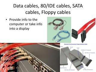
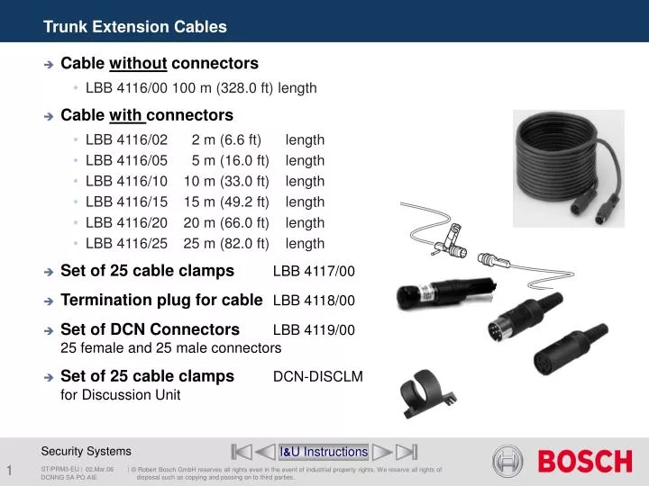
Trunk Extension Cables. Cable without connectors LBB 4116/00 100 m (328.0 ft) length Cable with connectors LBB 4116/02 2 m (6.6 ft) length LBB 4116/05 5 m (16.0 ft) length LBB 4116/10 10 m (33.0 ft) length LBB 4116/15 15 m (49.2 ft) length

E N D
Trunk Extension Cables • Cable without connectors • LBB 4116/00 100 m (328.0 ft) length • Cable with connectors • LBB 4116/02 2 m (6.6 ft) length • LBB 4116/05 5 m (16.0 ft) length • LBB 4116/10 10 m (33.0 ft) length • LBB 4116/15 15 m (49.2 ft) length • LBB 4116/20 20 m (66.0 ft) length • LBB 4116/25 25 m (82.0 ft) length • Set of25 cable clampsLBB 4117/00 • Termination plug for cableLBB 4118/00 • Set of DCN ConnectorsLBB 4119/00 25 female and 25 male connectors • Set of25 cable clampsDCN-DISCLM for Discussion Unit I&U Instructions DCNNG SA PO AIE
Extension Cable wiring PIN 1 - Down- link screen (ground) PIN 2 - Down- link signal data from CCU (green) PIN 3 - Positive supply (max. 40V) (brown) PIN 4 - Up- link- signal data to CCU (white) PIN 5 - Up- link screen (ground) PIN 6 - Positive supply (max. 40V) (blue) I&U Instructions DCNNG SA PO AIE
1 2 3 4 Trunk Splitter • 1 DCN cable A2 m long cable with a male connector. • 2DCN socket (trunk) A female socket for loop-through. • 3DCN socket (tap-off 1) A female socket to create a tap-off. The signal is automatically regenerated. • 4DCN socket (tap-off 2) A female socket to create a tap-off. The signal is automatically regenerated. Note: it’s never allowed to put trunk cables in parallel you always have to use aTrunk Splitter or Tap-Off Unit (Trunk Splitter Protected). LBB4114/00 tap-off 1 tap-off 2 I&U Instructions DCNNG SA PO AIE
Trunk-in Trunk-out ** * Tap-off outlets which regenerating the digital signal. * * Trunk Splitter • Two signal regenerated tap-off outlets. LBB4114/00 1 n n n I&U Instructions DCNNG SA PO AIE
1 2 3 4 Tap-off unit (Trunk Splitter Protected) • 1 DCN cable A2 m long cable with a male connector. • 2DCN socket (trunk) A female socket for loop-through. • 3DCN socket (tap-off 1) A female socket to create a tap-off. The signal is automatically regenerated. Furthermore, the tap-off is protected for short-circuits and has a maximum load of 4.5 W. • 4DCN socket (tap-off 2) A female socket to create a tap-off. The signal is automatically regenerated. Furthermore, the tap-off is protected for short-circuits and has a maximum load of 4.5 W. LBB4115/00 tap-off 1 tap-off 2 I&U Instructions DCNNG SA PO AIE
Trunk-in Trunk-out ** * * Tap-off unit (Trunk Splitter Protected) • Two signal regenerated AND protected tap-off outlets. LBB4115/00 Max. 4,5W Max. 4,5W 1 2 I&U Instructions DCNNG SA PO AIE
1 2 3 4 11 10 5 9 Description Numeric display Alpha-numeric display-1 with PC-only Alpha-numeric display-2 with PC-only Status display (GEO Vote) with PC-only Reserved Speak slowly singnaling Help signaling (booth 1 to 16) Help signaling (booth 17 to 31) 6 Data Distribution Board • 1DCN cable • A2 m long cable with a male connector. • 2J10 jumper • Two jumpers to select between system power supply or an external power supply. • 3S8 Dip switches • A series of dip switches to configure: I&U Instructions DCNNG SA PO AIE
Data Distribution Board 1 2 3 • 4RS232 To Numeric Hall Displays. (see next slide). • 5Input A 20-pole parallel input connector to connect external devices. • 6Input Twenty solder pads for customized parallel input solutions. • 7Output Twenty solder pads for customized parallel output solutions. • 8Initialization buttonA button to initialize the address of the board. Next to the button is a LED that indicates the non-initialized mode. 4 11 10 5 9 8 6 7 I&U Instructions DCNNG SA PO AIE
Numeric Hall Display with Data Distribution Board Voting timer Nevertheless the "voting time" is given by DCN but only with PC-control Address 248 DCN-DDB I&U Instructions DCNNG SA PO AIE
1 2 3 4 11 10 5 9 6 Data Distribution Board • 9Output A 20-pole parallel output connector to connect external devices. • 10Remote initializationA 10-pole connector for remote initialisation of the data distribution board. • 11External power supplyProvision to connect an external power supply to feed the data distribution board from an external power source instead of the system power supply. I&U Instructions DCNNG SA PO AIE
Push on Slow button DDB used for speak slowly signaling. Booth and desk # not important. The first activated Slow action activates the first bit DOO. When more Slow actions are activated at the same time more bits are activated. (max. 8) I&U Instructions DCNNG SA PO AIE
Push on Help button DDB used for Help signaling. Booth 3 desk # Desk # not important. The first activated Help action within the booth activates the corresponding bit. I&U Instructions DCNNG SA PO AIE
DDB used for remote functions. • External Switching device I&U Instructions DCNNG SA PO AIE
Optical Network Splitter • The Network Splitter is used to create short-circuit proof tap-off points in the optical network. LBB4410/00 I&U Instructions DCNNG SA PO AIE
4 5 6 3 7 2 8 1 Optical Network Splitter • 1External power supplyA socket for an (optional) external power supply (48 V DC). The external power supply only feeds the tap-offs. It does not provide power to the trunk line. • 2Tap-off 1 An optical network socket to create a tap-off. The tap-off is protected for short-circuits and has a maximum load of 2.5 A. • 3 Trunk An optical network socket to connect the network splitter to the optical network. • 4Lid A lid that provides access to the jumpers. The rear side of the lid contains a label with explanation about the internal settings. LBB4410/00 I&U Instructions DCNNG SA PO AIE
4 5 6 3 7 2 8 1 Optical Network Splitter • 5Status LED Yellow • 6Status LED Green • 7Trunk An optical network socket to connect the network splitter to the optical network. • 8Tap-off 2 An optical network socket to create a tap-off. The tap-off is protected for short-circuits and has a maximum load of 2.5 A. LBB4410/00 I&U Instructions DCNNG SA PO AIE
Optical Network Splitter internal settings LBB4410/00 I&U Instructions DCNNG SA PO AIE
Fiber interface without address • The fiber interface is used to convert from plastic optical fiber cable (POF) to glass optical fiber cable (GOF) and vice versa to cover distances of more than 50 m in the optical network. LBB4414/10 LBB4414/10 I&U Instructions DCNNG SA PO AIE
4 5 6 3 2 7 1 Fiber interface without address • 1External power supply A connection for an optional external power supply • 2Control inputs for future use. • 3 POF socket A POF socket to connect the Fiber interface to a POF cable. • 4Lid for future use. • 5 & 6Status LED’s See next slide • 7GOF socket A GOF socket to connect the Fiber interface to a GOF cable. LBB4414/10 I&U Instructions DCNNG SA PO AIE
Fiber interface without address Status LED,s 5 6 I&U Instructions DCNNG SA PO AIE
Accessories and Installation Equipment End of section SA PO Menu DCNNG SA PO AIE