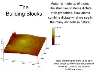
Download
1 / 51
550 likes | 783 Vues
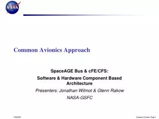
Common Avionics Building Blocks. Glenn.P.Rakow@nasa.gov Jonathan.J.Wilmot@nasa.gov. Background. Common avionics is a term used here to describe how to design space electronics and software for reuse between different space avionics makers

E N D
Common Avionics Building Blocks Glenn.P.Rakow@nasa.gov Jonathan.J.Wilmot@nasa.gov
Background • Common avionics is a term used here to describe how to design space electronics and software for reuse between different space avionics makers • This work stems from work on Constellation, specifically the former Altair project (Lunar Lander); NASA/GSFC software component based architecture, core Flight Executive (cFE); and Consultative Committee for Space Data Systems (CCSDS) Spacecraft Onboard Interface Services (SOIS) Working Group (WG) • DIMA is another term used to describe this work
What is DIMA? • Distributed • Resources (both hardware and software) are physically distributed • Reduce harness mass • Provide for local control of local functions • Lowers flight computer load • Integrated • Multiple functions of different criticalities running on separate, high integrity, partitions • Re-locatable functions not limited to a single line replaceable unit (LRU) boundary • Modular • Standard interfaces/Virtual Backplane • Avionics boxes built up of hub card(s), power supply(s) and subsystem slices • Provides for composability • Allows for hardware reuse • Software constructed of re-locatable modules • Allows for software reuse • Avionics • Board level building blocks used to assemble boxes into systems
DIMA Rationale • Significantly reduce Non Recurring Engineering (NRE) for the development, testing and integration of avionics systems • Design systems from software & hardware building block modules • Seamless integration of modules to form units and systems • Vendors can build building block products, e.g., electronic boards and software applications that can be rapidly integrated to form avionics boxes and systems • Everyone designing to the same interfaces for compatibility and interoperability • AFRL estimates 80-90% of mission costs are NRE
Key Technical Aspects of DIMA • Partition based software – time/space software partitioning (allows applications with different criticality levels to be hosted on same processor) • Component based software – modular software tasks integrated to software bus (supports easy development and integration of software due to independence of tasks and is the basis for distribution of software across different processors) • Data Exchange Message (DEM) format – provides message definition for parsing data across system. Allows packet wrapping and passing data across different layers • Time Triggered data bus (virtual backplane) • 10-20 x faster than current command & control bus (Mil-Std 1553) • fault tolerant Time Division Multiple Access (TDMA) data bus (no single component can take down bus) • Provides synchronization for data for software distribution and byzantine architecture • Board level building block elements • Enables random boards to be built into a variable length box with little/no NRE
Current Efforts for Space Common Avionics* • Air Force Research Lab (AFRL) Operational Responsive Space (ORS) Space Plug-n-Play Avionics (SPA) • Consultative Committee for Space Data Systems (CCSDS) Spacecraft Onboard Interface Services (SOIS) Working Group (WG) • European Space Agency (ESA) Space Avionics Open Interface aRchitecture (SAVOIR) * May be other efforts
A Past Effort • NASA HQ Standard Component Office – developed by GSFC • Defined complete Spacecraft bus • Flown on: • Solar Max • LandSat 4 • LandSat 5 • UARS • EUVE • TOPEX • GRO (electronics only) • HST (basic C&DH) • Government is the architect • Questions: • What should standardize and why?
What should we standardize and why? • Focus here is on avionics • Electronics will evolve and need to accommodate this trend • Currently designs are becoming IO bound • Density increases but power density is becoming issue • Believe electronics form factor can be selected • Standardize on interfaces and not on implementation • Layered architecture – easier to design, implement and test. Also easier to change a layer while minimizing affect on other layers • Protocol flexibility – across the communication stack • Standardize on lowest level of modularity • Software component • Hardward -board level
Figures of Merit (FOM) • Mass • Power (power relates to mass) • *ilities • Extensibility – allows for future growth – additions of new functionality or evolvolution/modification of existing functionality • Composability – ability to select and recombine elements in various combinations to meet specific requirements (modular and stateless) • Testability • Vendor specific independence – government is architecture – definition of interfaces at low level (software component and board level) so products can be seamlessly integrated
Software • What we need • Modular – tasks need to be developed independently • Tasks need to be protected from one another • Task need to be integrated seamlessly within the same processor or on another processor • Permits • Quicker development • Fault tolerance • Quicker integration • System wide processor load balancing • Benefit • Saves NRE, i.e., money
GSFC Flight Software Architecture • Project cFE/CFS • Platform-independent, mission-independent PnP flight software framework • Reusable core Flight Executive (cFE) and cFE-compliant applications • Goal: Significantly reduce cost and schedule for flight software systems • Goal: Increase reuse of flight and ground software components • Goal: Enable technology infusion and evolution • Status • cFE complete and in maintenance • Component applications developed as needed • Flown on Lunar Reconnaissance Orbiter (LRO) • Based-lined for all GSFC in-house spacecraft developments • In use or being evaluated at several other NASA centers, JSC, ARC, LaRC, KSC, MSFC, and APL • Collaborations • AFRL Space Plug-and-play Avionics (SPA) • Architecture has been discussed with James Lyke, Frederick Slane, Raymond Krosley • GPS and SpaceWire PnP discovery and Electronic Data Sheets(EDS) prototyping and demonstration • Reviewing AIAA SPA standards • CCSDS/ESTEC • Standardization of Spacecraft Onboard Interface Services SOIS
Files, Tables cFE Layered Component Architecture • Each layer and service has a standard API • Each layer “hides” its implementation and technology details. • Internals of a layer can be changed -- without affecting other layers’ internals and components. • Small-footprint, light-weight architecture and implementation minimizes overhead. • Enables technology infusion and evolution. • Provides Middleware, OS and HW platform-independence.
Typical Flight Components Analog I/O EPS HW Prop HW Digital IO GNC-G Application Prop Application Nav Fast Propagate Nav UPP GNC-C Application Nav – KF (Kalman Filter) Automated Flight Manager (AFM) 100 Hz 50Hz 100 Hz 1 Hz 1 Hz 100 Hz 25Hz 5 Hz GNC Sensors Mass Storage System SSR 1553 SIGI, 1553 IO 50 Hz GPS/SIGI GNC-N Apps Javad GPS 5 Hz 232 GPS IO C&T Application EPS Application Nav - IMU Preprocessor Data 10 Hz 50 Hz 50 Hz Storage 5 Hz Bkground 5 Hz 232 Altimeter Alt IO Health & 50 Hz Inter-task Message Router (SW Bus – Publish/Subscribe) LN200 IMU 422 Safety LN200 IO Manager 1 Hz Scheduler Limit Checker Table Telemetry Output Event Command Ingest House- keeping Time Executive Software Bus Services Services Services Services 5 Hz C&T Hardware, Radio 10 Hz 100 Hz 10 Hz 10 Hz (Framed CCSDS) cFE Core Services Mission Specific I/O Apps CFS Configurable Applications Mission Specific Apps
Software Support for Distributed IMA • Virtual partitioning: • Single CPU: • CPU failure takes down everything • Partitioned into multiple virtual CPUs: • Space and time partitioning ARINC-653 • Requires a high-performance processor • Distributed partitioning: • Multiple CPUs: • CPU failure has limited affectivity • Real partitioning: • Space - geographical separation • Time - TDMA system bus behavior • Machines can be scaled to requirements: • Low-power, rad-hard • Multi-core partitioning: • A form of distributed processing • Use case: Image processing for landing and docking • Multi-core scenario • Systems can be built from a combination of these approaches • Proper interface definition allows software and hardware components to be minimally affected by these partitioning trades
DIMA Enabled RIU Controller • Partitioned run-time hypervisor on a microcontroller • Time slice via configuration table on interrupt driven minor cycles • MMU isolation of component memory, I/O access, and Interrupt Service Routines (ISR) • Components only have access to their memory and I/O space • Run-time and I/O schedules are Time-Triggered to bound latency • Hypervisor controls bus interfaces and ISRs • Application initiated processor exceptions are masked, but counted for diagnostics • Hypervisor can interrupt components only as configured • Hypervisor supports common load, initialization, controller diagnostics, configuration… ATCS C&DH ATCS C&T ECLSS Power GN&C Mech Prop Unknown RIU maintains system composability
HardwareGlenn.P.Rakow@nasa.govAlex.Kisin@nasa.govEric.T.Gorman@nasa.govHardwareGlenn.P.Rakow@nasa.govAlex.Kisin@nasa.govEric.T.Gorman@nasa.gov
Problem • This presentation address how to build avionics boxes from modular board level elements • Intra-box only • To significantly reduce NRE of development, test and integration and through eventual reuse • It does not address the box-to-box communication physical interface or protocol, i.e., does not address Inter-box • This approach can support different data link layer protocols
Focus • Need to be applicably to wide range of requirements (90% rule) • Robotic and Human rated • Centralized and Distributed • Support different redundancy schemes • Single string, Block Redundant, Cross-Strapped Redundant • Implementation agnostic (vendor agnostic) • Need to focus on interface definitions and be protocol agnostic. • Interface definitions need to be defined along the computer communication stack so that different layers may be substituted without effecting layers above and below, e.g., 1553 can be replace by TTP/C or TTGbE, etc. • Define Intra-box physical interfaces only and not protocol or voltage levels – let community sort this out and converge
Approach • Dominate FOMS – mass and power • Eliminate NRE of backplane and mechanical chassis • Quickly accommodate boxes of varying module count
Goal • Multiple vendors can build and qualify their board level building block (including software because time-space partitioned) without knowing what other boards in box will be or how many
Signal Buses Traditional Approach • Electrical • Custom and/or Euro Card form factor (typically 6U or 3U) • Single sided or double sided boards • Parallel Printed Wiring Board backplane (derived from commercial world) • Some custom signals added to standard signal set (PCI, VME, etc.) making interchangeability difficult • Mechanical • Custom Enclosure design with card faceplate integrated with card • Wedge locks for card locking and heat dissipation path: • From board to wedge lock • From wedge lock to overall enclosure • From enclosure to chassis • Qualification • Modules are integrated into enclosure are only functionally tested • Environmental testing (EMI/EMC, thermal, vibration) is done on box level
Design Goals • Create architecture suitable for 90% of space missions • Reduce costs avionics system development • Throughsignificant reduction of NRE and • Through standardization of avionic internal electrical interfaces and mechanical interfaces • Simplify electrical interfaces by adopting: • Serial communications interface • Eliminate mechanical tolerances between backplane connectors and boards • Increase system reliability by reducing number of signals • Single voltage power distribution • Higher voltages to reduce current and eliminate voltage margin concerns • Minimal set of commonly used signals • Interconnection through a star architecture • Common or Central module – HUB • Peripheral or User module – NODE • Simplify mechanical interfaces by adopting: • Modular and variable length slot mechanical enclosure concept using card frames (slices) where: • Each Printed Wiring Board (PWB) includes its own portion of the mechanical chassis • Improvement of thermal design – eliminates wedge locks as thermal path • Qualifies modules (slices) for EMI/EMC and thermal requirements • Significantly reduces tolerance of mechanical design
Major System Requirements • High speed communication links • Compatibility with high speed (gigabit) serial protocol • Power distribution • Reliability • module-to-module isolation • Support Redundancy schemes • Ease of implementation • Minimal compatibility requirements • Simple predefined interfaces • Ease of expansion • Up to 7 NODE modules in same chassis (8 or 9 modules total including HUB module(s)) • At least 1 surface reserved for user connectors
Proposed System Functions • Data • Serial communications from HUB to each NODE • Data rates per link: from 1Mbps to up to 3.125Gbps (user configurable and programmable) • Differential pairs for Full duplex operations • Multiple streams: HUB can talk simultaneously to more than one NODE • Flexible data transfer protocols such as SpaceWire, SpaceFibre, PCI Express, etc: all can co-exist in 1 system • AC coupling for better CMV protection • Power • 28V bus switched power distribution from HUB • Up to 20-30W RMS power per NODE • Electrical isolation between Hub(s) and Nodes • True “hot” plugging/unplugging for all NODEs and HUBs without disturbing other system components • Capability to work directly with 120V power bus voltages • Clock • Individually distributed from HUB to each NODE • User programmable clock distribution for S/C events synchronization • Single frequency power supplies synchronization • Analog telemetry • HUB will process all Node telemetry (with 0.1% accuracy); Node requires to have: • Either differential multiplexer and signal scale conditioner for NODE analog signals (0.1% accurate) , or • Single thermistor, if any NODE analog circuitry is undesirable • Auxiliary • Complete all in-system functions programming and debugging • Visual indication to show activity of any HUB or NODE modules
Proposed System Highlights • Ease of implementation • Simple electrical interface • Only 16 physical copper wires per link which are capable to satisfy requirements for 90% or more missions • Simple mechanical interface • Only connectors position is defined • No restrictions for module width • Much easier compatibility between various vendors • No custom user functions for standardized back connectors • Increased data throughput on subsystem level • Serial links will provide higher data rates • Double processing/communication rate when 2 HUB modules are plugged in • User expandability • Front and Top surfaces are reserved for User connectors • Multiple cards per module • Lower mass and volume over parallel bus design • Superior heat transfer • Elimination of wedge locks: direct contact between cards and module’s frame • Larger contact surfaces between module body and chassis • EMI/EMC issues • 100% EMI shielded • Lower emitted noise due to a possible total synchronization of all units • System reliability • Single string, or • Dual independent redundancy, or • System cross-redundancy • Wide range of applications • Can be used for human or robotic missions
Connector’s Desired Requirements • Minimum number of conductors • 16, with capability of expansion • Wires • Up to AWG#24 wires for power transfer • Impedance • 100 ohms differential • Termination • Customer controlled • Shielding • 100% EMI shielded • Connectivity • Blind mateable • Scoop proofed • Material • No outgassing and wiskering • Shape • Rectangular for small real estate use
Suggested Connector Type Rugged D-Sub miniature from Sabritec Inc. with Quadraxial pin assembly inserts 4 (shown) and 16 position shells are suggested
Dual Cards Assembly for HUB Module (with EMI shield)
Dual Cards Assembly for HUB Module (without EMI shield)
Single Cards Assembly for Node Module (without EMI shield)
Single Cards Assembly for Node Module (with EMI shield)
Assembled System View (with EMI shield)
Assembled System View (without EMI shield)
Assembled System View with End Plates (without EMI shield)