Download
1 / 16
170 likes | 338 Vues
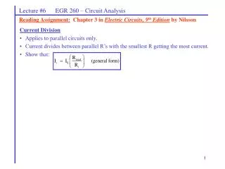
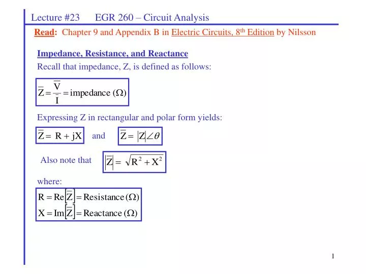
Lecture #23 EGR 260 – Circuit Analysis. Read : Chapter 9 and Appendix B in Electric Circuits, 8 th Edition by Nilsson. Impedance, Resistance, and Reactance Recall that impedance, Z, is defined as follows:. Expressing Z in rectangular and polar form yields:. and. Also note that.

E N D
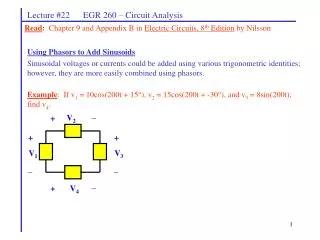
Lecture #23 EGR 260 – Circuit Analysis Read: Chapter 9 and Appendix B in Electric Circuits, 8th Edition by Nilsson Impedance, Resistance, and Reactance Recall that impedance, Z, is defined as follows: Expressing Z in rectangular and polar form yields: and Also note that where:
Im Z X |Z| Re R |Z| jX R Lecture #23 EGR 260 – Circuit Analysis Impedance Diagram: The relationship between Z, R, and X is sometimes illustrated using an impedance diagram as shown: or Inductive reactance: Recall that the impedance for an inductor was defined as: So inductive reactance is defined as follows: or
I + V _ Lecture #23 EGR 260 – Circuit Analysis Capacitive reactance: Recall that the impedance for a capacitor was defined as: So capacitive reactance is defined as follows: or • Example: • If w = 100 rad/s, find: • The resistance of the circuit • The reactance of the circuit • If the impedance is to be represented by a series RC circuit, find R and C • If the impedance is to be represented by a parallel RC circuit, find R and C
() () () Lecture #23 EGR 260 – Circuit Analysis Admittance, Conductance, and Susceptance Admittance is defined as follows: Expressing Y in rectangular form yields: where: Note that G and B can be expressed in terms of R and X as follows: so
Example: If w = 10 rad/s for the circuit shown, find Z, |Z|, R, X, Y, G, and B I + V 10uF 1.5k _ Lecture #23 EGR 260 – Circuit Analysis
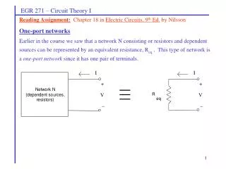
Lecture #23 EGR 260 – Circuit Analysis • Thevenin’s & Norton’s Theorems • Recall that any one-port network N may be represented by either of the following: • Thevenin Equivalent Circuit (TEC) – consisting of a voltage source and a series impedance • Norton Equivalent Circuit (NEC) – consisting of a current source and a parallel impedance
Lecture #23 EGR 260 – Circuit Analysis Example: Find the TEC seen by the load in the circuit shown below.
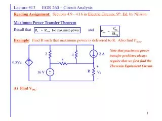
Network N For what load is maximum power delivered to the load? independent sources, Z L dependent sources, What is the maximum power? resistors, inductors, and capacitors Lecture #23 EGR 260 – Circuit Analysis Maximum Power Transfer Theorem This transfer theorem states that maximum power is delivered to the load when And that the value of the maximum power is
Example: For what value of ZL is maximum power delivered to ZL? What is the maximum power? (Note: This is the same circuit used in the last example.) Lecture #23 EGR 260 – Circuit Analysis
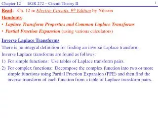
Lecture #23 EGR 260 – Circuit Analysis Resonance – the condition where the reactive components in a circuit cancel resulting in a purely resistive circuit. This condition can sometimes yield unusually large voltages or currents. Series resonant circuit: Show that
Lecture #23 EGR 260 – Circuit Analysis Series Resonant Circuit: (continued) Solve for the current and all component voltages both as phasors and functions of time. Sketch the time waveforms.
Lecture #23 EGR 260 – Circuit Analysis Series Resonant Circuit: (continued) Define Qs = “Quality factor” for a series resonant circuit. Show that
Lecture #23 EGR 260 – Circuit Analysis Example: Determine wo , fo , Qs , Zeq , I, VR , VL , and VC for a series resonant circuit using R = 4 ohms, C = 1 F, L = 10 mH, and Vs = 100V. Sketch a phasor diagram illustrating the relationship between the voltages in the circuit.
Lecture #23 EGR 260 – Circuit Analysis Parallel resonant circuit: Show that Also determine expressions for resistor, capacitor, and inductor current.
Lecture #23 EGR 260 – Circuit Analysis Resonance in other circuits The relationships developed for wo for series and parallel RLC circuits do not apply to other resonant circuits. The value of wo can be determined for other circuits by finding the total circuit impedance and determining at what frequency the total circuit impedance is real. Example: Find the resonant frequency, fo, for the circuit shown. Compare the result to the incorrect value obtained by using the relationship for fo for a series or parallel RLC circuit.