Download
1 / 1
30 likes | 159 Vues
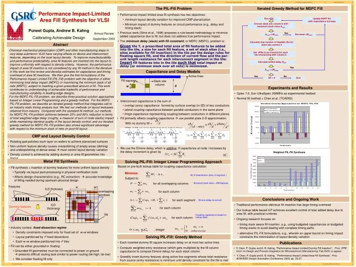
Choose slack site column k with maximum slack value S max. S max < LB slack. D add > UB delay. Run STA. Get #fills to be inserted for each tile intersecting with column k. Calculate added delay D add. Calculate max number of feasible fills for slack site column k. tile.

E N D
Choose slack site column k with maximum slack value Smax Smax< LBslack Dadd > UBdelay Run STA Get #fills to be inserted for each tile intersecting with column k Calculate added delay Dadd Calculate max number of feasible fills for slack site column k tile Update RSPF file with capacitance increase Decrease LBslack DF > 0 Active lines Fill squares Slack site column d w Features w w/r ILD thickness ILD thickness Dummy features The PIL-Fill Problem Iterated Greedy Method for MSFC Fill Performance Impact-Limited Area Fill Synthesis for VLSI • Performance-impact limited area fill synthesis has two objectives: • minimum layout density variation for improved CMP planarization • Minimum impact of dummy features on circuit performance (e.g., delay and timing slack) • Previous work (Stine et al., 1998) proposes a rule-based methodology to minimize added capacitance due to fill, but does not address true performance impact. • The minimum delay (slack) with fill constraint, or MDFC (MSFC), problem is: • Given tile T, a prescribed total area of fill features to be added into the tile, a size for each fill feature, a set of slack sites (i.e., sites available for fill insertion) in the tile per the design rules for floating square fill, and the direction of current flow and the per-unit length resistance for each interconnect segment in the tile: Insert fill features into in the tile such thattotal impact on delay (or minimum slack over all nets) is minimized. Puneet Gupta, Andrew B. Kahng Calibrating Achievable Design Annual Review September 2003 Yes Abstract Chemical-mechanical planarization (CMP) and other manufacturing steps in very deep-submicron VLSI have varying effects on device and interconnect features, depending on the local layout density. To improve manufacturability and performance predictability, area fill features are inserted into the layout to improve uniformity with respect to density criteria. However, the performance impact of area fill insertion is not considered by any fill method in the literature. In this work we first review and develop estimates for capacitance and timing overhead of area fill insertions. We then give the first formulations of the Performance Impact Limited Fill (PIL-Fill) problem with the objective of either minimizing total delay impact (MDFC) or maximizing the minimum slack of all nets (MSFC), subject to inserting a given prescribed amount of fill. This work contributes to understanding of achievable tradeoffs of performance and manufacturing variability in leading-edge designs. For the MDFC PIL-Fill problem, we describe three practical solution approaches based on Integer Linear Programming and a greedy method. For the MSFC PIL-Fill problem, we describe an iterated greedy method that integrates call to an industry static timing analysis tool. We test our methods on layout testcases obtained from industry. Compared with the standard fill method, our methods for MDFC PIL-Fill problem achieves between 25% and 90% reduction in terms of total weighted edge delay (roughly, a measure of sum of node slacks) impact while maintaining identical quality of the layout density control; and our iterated greedy method for MSFC PIL-Fill problem also shows significant advantage with respect to the minimum slack of nets on post-fill layout. Yes Capacitance and Delay Models Yes No • Interconnect capacitance is the sum of • overlap (area) capacitance formed by surface overlap (in 2D) of two conductors • lateral coupling capacitance between parallel conductors in the same plane • fringe capacitance representing coupling between conductors in different planes • Fill primarily affects coupling capacitance use parallel plate 2-D approximation • With no dummy fill = • With m fill squares between two active lines = • We use the Elmore delay, which is additive: If capacitance at node i increases by the delay increment is given by End Experiments and Results • Cplex 7.0, Sun UltraSparc 300MHz as experimental testbed • Normal fill method = Chen et al. (TCAD02) CMP and Layout Density Control • Rotating pad polishes each layer on wafers to achieve planarized surfaces • Non-uniform feature density causes overpolishing of empty areas (dishing) and underpolishing of dense areas must control layout density variation • Density control is achieved by adding dummy or areafill geometries into layout Metal Fill Synthesis Solving PIL-Fill: Integer Linear Programming Approach Based on pre-built lookup table for coupling capacitance calculation • Fill synthesis = insertion of dummy features for more uniform layout density • Typically via layout post-processing in physical verification tools • Affects design characteristics (e.g., RC extraction) accurate knowledge of filling needed during upstream physical design Minimize: Wl: # downstream sinks of segment l Subject to: for all overlapping columns #covered slack sites = #fill features overlapping windows for each column Conclusions and Ongoing Work for each segment Elmore delay increment • Traditional performance-oblivious fill insertion has large timing overhead • Our lookup table based ILP achieves excellent control of total added delay due to area fill, with practical runtimes • Ongoing research focuses on: • timing slack aware fill insertion, e.g., using budgeted capacitances or budgeted timing slacks to avoid dealing with complete timing paths • alternative PIL-Fill formulations, e.g., wherein an upper bound on timing impact constrains the minimization of layout density variation for each column Coupling capacitance based on lookup table for each column • Industry context: fixed-dissection regime • Density constraints imposed only for fixed set of ww windows • Layout partitioned by r2 fixed dissections • Each ww window partitioned into r2 tiles • Fill can be either grounded or floating • Grounded fill geometries must be connected to power or ground presents difficult routing task similar to power routing (tie-high, tie-low) • We consider floating fill only , integer Solving PIL-Fill: Greedy Method • Each inserted dummy fill square increases delay on at most two active lines • Compute weighted entry resistance (which gets multiplied by the fill column capacitance to compute Elmore delay) for each slack column • Greedily insert dummy features along active line segments whose total resistance from source (entry resistance) is minimum until density constraint for the tile is met Publications • Y. Chen, P. Gupta, and A. B. Kahng, “Performance-Impact Limited Dummy Fill Insertion”, Proc. SPIE Conf. on Design and Process Integration for Microelectronic Manufacturing, Feb 2003, to appear. • Y. Chen, P. Gupta and A. B. Kahng, “Performance-Impact Limited Area Fill Synthesis”, Proc. ACM/IEEE Design Automation Conference, 2003, pp. 22-27.