Download
1 / 38
380 likes | 469 Vues
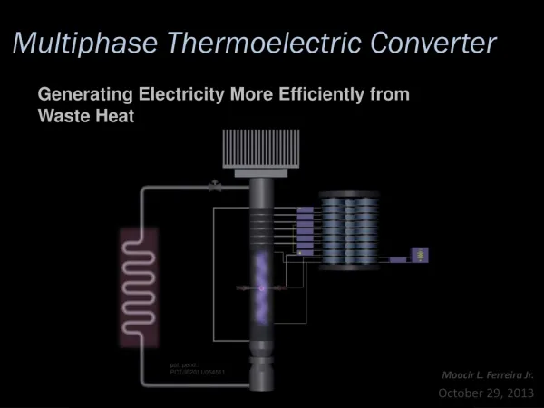
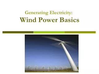
Generating Electricity. COMBINED-CYCLE PLANT. Combined heat and power – fuller utilization of heat. Appropriate in high density places Don’t “add” efficiencies. Calculate utilization , ε :. Energy conversion. Thermal energy converted to motion using turbine

E N D
Combined heat and power – fuller utilization of heat • Appropriate in high density places • Don’t “add” efficiencies. Calculate utilization, ε :
Energy conversion • Thermal energy converted to motion using turbine • Steam – Steam-Turbine-Generator • Combustion gases – Gas-Turbine-Generator • Turbine subject to device efficiency and Carnot efficiency • Motion of turbine blades • Rotates the shaft of electric generator • Converts the rotational energy into electricity
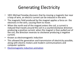
Faraday’s law where |e| is the “electromotive force” (“emf” is also what we call “Voltage”) Easy way to get df/dt: Move conductor through magnetic field (or move mag. field)
Flux linkages and Faraday’s Law If magnetic flux links an N turn coil Where V is the voltage and l is the flux linkage If all flux links all turns then l=Nf
Mnagnetic cores To ensure all magnetic flux flows through coils we employ “magnetic core” • High magnetic permeability material • Guide magnetic fields through electrical devices • Usually made of ferromagnetic metal such as iron (steel)
Multiple pole generator • The following figure shows a 2-pole and a 4-pole synchronous generator
Magnetic Excitation Rotor is electromagnet, contains “field windings”
Rotation Speed The frequency of generated voltage in U.S. is 60 Hz • Europe, Japan = 50Hz Therefore, the shaft of generator must turn at a certain speed: NS is called the synchronous speed
Increasing number of poles Increasing number of poles increases number of times magnetic flux changes per revolution of the rotor. Synchronous spped depends on number of poles (p) and output frequency (f) Allows shaft to turn slower (easier to build/maintain)
Generating three phase power Three voltage sources with equal magnitude, but with an angle shift of 120
Advantages of 3 Power Can transmit more power for same amount of wire (twice as much as single phase) Torque produced by 3 machines is constant Three phase machines use less material for same power rating Three phase machines start more easily than single phase machines
Balanced 3 Phase (3) Systems 3 phase system has equal loads on each phase equal impedance on the lines connecting the generators to the loads Bulk power systems almost exclusively 3 Single phase is used in low voltage, low power settings (e.g., residential, light commercial)
Power transmission • Generation: 2.3 to 30 kV
TRANSMISSION GRID • The following figure shows the one-line diagram of an HVDC link
TRANSMISSION LINES • The following figure shows the tower configurations
Frequency Control Steady-state operation only occurs when the total generation exactly matches the total load plus the total losses too much generation causes the system frequency to increase too little generation causes the system frequency to decrease (e.g., loss of a generator) AGC is used to control system frequency
Power transmission Generation: 2.3 to 30 kV, Transmission: 138 kV to 765 kV (why?)
Transformers Overview Power systems have many different voltages 765 kV down to 240/120 volts. Ability of simple change of voltage levels is the key advantage of AC over DC systems Transformers are used to transfer power between different voltage levels
Transmission Level Transformer 230 kV surge arrestors 115 kV surge arrestors Oil Cooler Radiators W/Fans Oil pump
Ideal Transformer • Let’s examine an ideal transformer • no real power losses • magnetic core has infinite permeability • no leakage flux • Nomenclature I may use: • “primary” side is “power in” • “secondary” is “power out”
Flux linkages and Faraday’s Law If magnetic flux links an N turn coil Where V is the voltage and l is the flux linkage If all flux links all turns then l=Nf
Residential Distribution Transformers Single phase transformers used in residential distribution systems Most distribution systems are 4 wire, with a multi-grounded, common neutral