Download
1 / 19
190 likes | 299 Vues
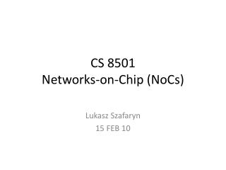
Networks-on-Chip. ECE 111. Many-Core Processor Roadmap. Number of cores Quadrupling every 3 years. ‘05. ‘08. ‘11. ‘14. ‘02. Research. 64. 256. 1024. 4096. 16. Industry. 16. 64. 256. 1024. 4. Source: Agarwal, MIT. Intel’s 80 core. Tilera’s 100 core. Cisco’s 188 core.

E N D
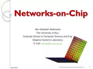
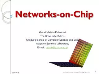
Networks-on-Chip ECE 111
Many-Core Processor Roadmap • Number of cores Quadrupling every 3 years ‘05 ‘08 ‘11 ‘14 ‘02 Research 64 256 1024 4096 16 Industry 16 64 256 1024 4 Source: Agarwal, MIT Intel’s 80 core Tilera’s 100 core Cisco’s 188 core
SoC & Many-Core Convergence • Application-Specific Systems-on-Chips (SoCs) are evolving to look like many-core processors with custom hardware cores Source: Arvind, MIT General-purposeprocessors Application-specificprocessing cores On-chipmemory cores Structured on-chip interconnection network
The Need for On-Chip Networks Compute or Memory Core Router Scalable communication Efficient use of wires Modular design A new way to organize and build VLSI systems
Power and Performance Both Critical Compute or Memory Core Router For most applications, low energy consumption and high-performance are both 1st order design goals ! e.g. 28% of total power in Intel 80-core Teraflops chip is due to interconnection networks (routers + links); Network latency plays central role in performance
Flits • Packets decomposed into “flits” • Basic data units • Flit size usually the same as “bus width”, say 128-bits • Head flit carries destination address information • Flow control • For on-chip networks, data loss is usually not acceptable • Credit-based flow control is used to ensure next-hop router has buffer size before a flit gets forwarded • Flits proceed forward like a “train” or “worm” through a path of routers • No need for store-and-forward, which leads to much lower latencies
Using Virtual Channels to Avoid Deadlocks Coupling between channels and buffers causes head-of-line blocking as well as deadlocks Adds false dependencies between packets, leading to possibly deadlocks Limits channel utilization Increases latency Solution: Implement virtual channels (VCs) Source: Becker et al, Stanford
VC Router Pipeline Route Computation (RC) Determine candidate output port(s) and VC(s) Can be precomputed at upstream router (lookahead routing) Virtual Channel Allocation (VA) Assign available output VCs to waiting packets at input VCs Switch Allocation (SA) Assign switch time slots to buffered flits Switch Traversal (ST) Send flits through crossbar switch to appropriate output Per packet Source: Becker et al, Stanford Per flit
Allocation Basics Arbitration: Multiple requestors Single resource Request + grant vectors Allocation: Multiple requestors Multiple equivalent resources Request + grant matrices Matching: Each grant must satisfy a request Each requester gets at most one grant Each resource is granted at most once Source: Becker et al, Stanford
Separable Allocators Matchings have at most one grant per row and per column Implement via to two phases of arbitration Column-wise and row-wise Perform in either order Arbiters in each stage are fully independent Fast and cheap But bad choices in first phase can prevent second stage from generating a good matching! Input-first: Output-first: Source: Becker et al, Stanford
Oblivious Routing • Route packets without knowledge about the state (e.g. congestion) of the network • Objectives • Maximize worst-case and average-case throughput • Minimize latency (hop count)
Routing Algorithm Affects Channel Loads Source: Seo et al, Purdue
DOR • DOR = Dimension Ordered Routing (XY Routing) • Minimal latency, no path diversity; hence poor worst case throughput and average case throughput Destination Y Source X
VAL • VAL = Valiant’s routing algorithm • Average latency twice as DOR, optimal worst-case throughput, poor average-case throughput Random Intermediate node Destination Y Source X
ROMM • ROMM • Minimal latency, good average throughput, but poor worst-case throughput Intermediate node within bounding box Destination Bounding Box Y Source X
O1TURN • O1TURN = Orthogonal 1 TURN (X-Y and Y-X routing with equal probability) • Minimal routing, optimal worst-case throughput, good average-case throughput Destination Y Source X
Worst-Case Throughput Trends Source: Seo et al, Purdue
Average Case Analysis Source: Seo et al, Purdue
Comparison DOR VAL ROMM O1TURN Minimal hop count X X X Worst-case Throughput X X Average-case Throughput X X X