Download
1 / 10
100 likes | 202 Vues
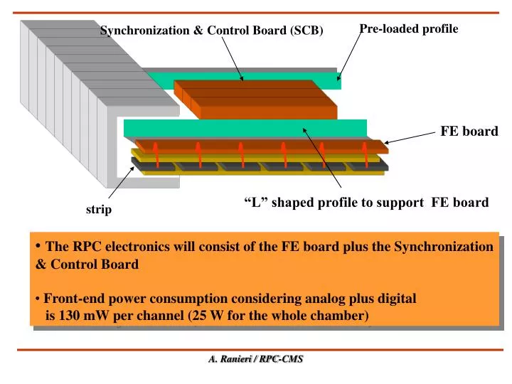
Pre-loaded profile. Synchronization & Control Board (SCB). FE board. “L” shaped profile to support FE board. strip. The RPC electronics will consist of the FE board plus the Synchronization & Control Board Front-end power consumption considering analog plus digital

E N D
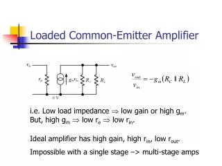
Pre-loaded profile Synchronization & Control Board (SCB) FE board “L” shaped profile to support FE board strip • The RPC electronics will consist of the FE board plus the Synchronization & Control Board • Front-end power consumption considering analog plus digital • is 130 mW per channel (25 W for the whole chamber) A. Ranieri / RPC-CMS
12 flat cables per station from FEB to SCB “L” shaped profile to support FE board FE board Optical link LB Clock line SCB Synchronization & Control Board (1 or 2/layer) DCS line SCB Data Line
FE Board Layout 8 8 FEC+DAC test point FEC+DAC test point DAC DAC Voltage Regul Voltage Regul FEC FEC 4 4 4 LVDS-R LVDS-R LVDS-R 16 LVDS output DCS from SCB A. Ranieri / RPC-CMS
Synchronization & Control Board (SCB) Channel Link (x6) Twin Coax To LB Synchro & FIFO CDC 509 Ck1 96 LVDS-R (x 24) Signal In from FEC Synchro & FIFO CDC 509 DLL MCK from LB Ck2 48 LVDS-D (x 12) Test Out from FIFO Synchro & FIFO CDC 509 TS 24 DCS Bus LVDS-D (x 6) DCS chip set DCS out for DAC A. Ranieri / RPC-CMS
HV System requirements • Maximum number of HV channels ~ 4000 • Max value = 12.000 V • Imax = .5 mA/channel • Magnetic field inside ironB = 1.8 Tesla • Possibility to switch off one sub-channel only • Single rate counting for each sub-channel: (desirable) • Rad-hard devices necessary ? (not necessary for RPC) • Fault tolerant system (redundancy): (desirable) • HV & LV system crates on the balcony around the detector RPC_CMS HV & LV Distribution A. Ranieri / RPC-CMS
RPC sector in the Barrel LV analog LV digital 4 LV Ch. MB4 96 channels 96 channels 8 HV Ch. 4 LV Ch. MB3 8 HV Ch. 96 channels 96 channels 96 channels + 96 channels MB2 8 HV Ch. 4 LV Ch. 96 channels + 96 channels LV Channel HV Channel 96 channels + 96 channels MB1 8 HV Ch. 4 LV Ch. 96 channels + 96 channels 12 groups of 96 channels to be powered to LV, grouped into 16 LV channels Current absorption : .5 mA / HV Channel RPC_CMS HV & LV Distribution A. Ranieri
HV SY1527 possible segmentation 8 Ch RDB 1 SY1527 1 Crate/4 RPC sectors Ch. 1 (2 slot) (HV) Ch. 2 8 Ch Ch. 3 RDB 2 Ch. 4 Ch. 5 RDB=Remote Distribution Board Ch. 6 Ch. 7 8 Ch Ch. 8 8 Ch (HV) In the ipothesys of 12KV/sub-channel
HV SY1527 possible segmentation for HV & LV (Barrel case) • Considering: • 16 sub-channels (2 RDB - 8 ) / 2 HV slot • 16 sub-channels x 0.5 mA = 8 mA • 8 x 8 mA x 12 KV = 768 W/crate/ 4 sectors • 60 sectors : 4 = total of 15 SY1527 for HV only • 25 W x 12 = 300 W/ sector • 300 W x 60 = 18000 W : 2000 W = 9 SY1527 for LV only RPC_CMS HV Distribution A. Ranieri
Number of parameters to be controlled • 2000 digital words to be monitored as threshold values for a total of 13000 FE Boards for the entire detector (assuming to have only one threshold value for a group of 6 boards) • pulse width coming from the discriminator, fixed at 100 ns • number of temperature sensor = 1 / SCB (1/RPC layer) • Dead Channels: implementation of a digital mask on the synchronizer, to switch off dead channels RPC_CMS Calibration & Monitoring
RPC FE Electronics milestones • NewFE chip prototype: end of March 99 • chip test on new FE board(LAB): end of March 99 • chip pre-production: May 99 • test of chip pre-production: June 99 • new FE board pre-production & mounting: June-July 99 • test at CERN: July-September 99 • final production of FE: June 2000 • SCB prototype development: October 99 RPC FE Milestones