Download
1 / 43
430 likes | 512 Vues
Graduation Project DC POWER SUPPLY 12 V- 3A. *Supervised by : Prof. Marwan Mahmoud. *Prepared By : Esra’ Khader & Mohaia Eshtawe. Project Goals :.

E N D
Graduation Project DC POWER SUPPLY12 V- 3A *Supervised by : Prof. Marwan Mahmoud *Prepared By : Esra’ Khader & Mohaia Eshtawe
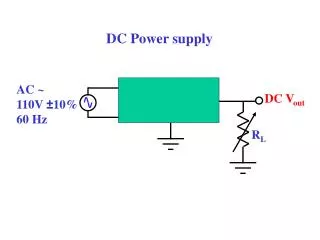
Project Goals : • To construct a regulated DC power supply 12 V / 3A source . the power supply converts the (220-230) V AC into(12 V – 3A) DC output . • To simulate PV module output (adjustable current & voltage) in the laboratory . • Establishment of a possibility Useful for testing of charge regulator being used in PV system .
Introduction • For electronic circuits made up of transistors and/or ICs, this power source must be a DC voltage of a specific value. • A regulated power supply is one that controls the output voltage or current to a specific value; the controlled value is held nearly constant despite variations in either load current or the voltage supplied by the power supply's energy source.
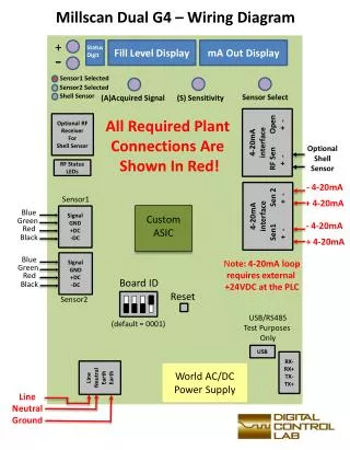
Transformer • how we select the transformer ? Transformer specification N1 902/Ø 0,4mm N2 70/Ø 1.2mm N3 58/Ø 0.224mm
Transformer • we add protection to the circuit ,we use fuses one at the input of the circuit before the transformer 400mA , and another one after the rectifier 4A they will break if current increases for any reasons and protect our circuit.
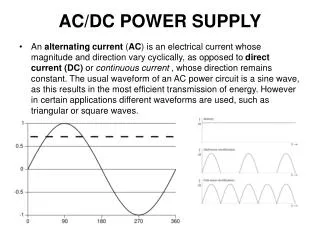
The rectifier converts the AC sine wave into a pulsating DC wave. • We use Full-wave rectification because it converts both polarities of the input waveform to DC (direct current), and it is more efficient.
Rectifier Average voltage Average voltage
Why we want to remove the ripple ? • The presence of ripple can reduce the resolution of electronic test and measurement instruments. On an oscilloscope it will manifest itself as a visible pattern on screen. • Within digital circuits, it reduces the threshold, as does any form of supply rail noise, at which logic circuits give incorrect outputs and data is corrupted. • High amplitude ripple currents reduce the life of electrolytic capacitors.
Ripple: • The varying DC output is suitable for lamps, heaters and standard motors. • It is not suitable for electronic circuits unless they include filter. • Our filter is very large capacitor(C=1mF) called smoothing capacitor. • We estimate the value of the capacitor according to the following equation:
Where : constant value t: discharge time of the capacitor u: ripple voltage • The smooth DC output has a small ripple. It is suitable for most electronic circuits.
Ripple calculation in our circuit: From table of standard value we use C=1mF
A filter is used to remove the pulsations and create a constant output. • Smoothing is performed by filter (1mF capacitor) connected across the DC supply to act as a reservoir, supplying current to the output when the varying DC voltage from the rectifier is falling. The capacitor charges quickly near the peak of the varying DC, and then discharges as it supplies current to the output.
Regulator: • The regulator fixes the output voltage to the desired level then maintains that value despite any output or input variations. • Regulated circuit we use simple Zener diode
Regulator: • The regulated DC output is very smooth with no ripple. It is suitable for all electronic circuits.
The regulated DC output is very smooth with no ripple. It is suitable for all electronic circuits.
Inter Mediate Stages • Operational amplifier: Used with this special Connection for distortion Cancellation
We measure the output • Voltage: The maximum value we could reach is about 11v (it was changing between 1.5 v – 11 v) • Current: The maximum value we could reach is about 600 mA (it was changing between micro amperes – 600 mA)
Conclusion: • After all work we did on our project we have learned so many things : • We always see A DC power supplies in laboratories and a DC charger for example for mobiles, laptops, cameras and so many things… It is the first time we learnt about its major stages. • it is the first time that we deal with transformer in these details . • we have studied the rectifiers in Power Electronics course but it is the first time we see the output at the oslliscope by our work. • we notice what useful we get from using a fuses for protection. • It is the first time we deal with many IC’s we studied in many courses like(power transistors ,operational amplifier ,zener diodes ,etc…)
Mistakes we did: • the first time we switch on the transformer it is secondary output wires touch each other and make short circuit but fortunate the fuse break and protect the transformer. • we have faced so many welding problems. • we use a npn transistor instead of pnp and this force us to reconnect our project.
Problems we face : • we couldn’t find some of IC’s so we use it’s complementary • lack of equipment and instruments in the workshop
Future stages • Micro-controller If a design pic micro controller added that will work as indicator for the situation of the DC power supply (KWh , Output current, output voltage especially by charging a battery)
Finally: QuEsTiOnS