Download

1 / 43
1.15k likes | 3.5k Vues
Chapter 3.2 : Heat Exchanger Analysis Using -NTU method. The Effectiveness-NTU Method: The rate of heat transfer in parallel-flow as well as counter-flow heat exchangers is given by same heat balance. In case of a counter-flow heat exchanger,

E N D
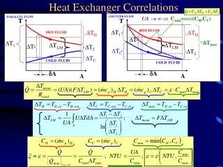
The Effectiveness-NTU Method: The rate of heat transfer in parallel-flow as well as counter-flow heat exchangers is given by same heat balance. In case of a counter-flow heat exchanger, The maximum temperature difference in a heat exchanger is the difference between the inlet temperatures of the hot and cold fluids. That is, ΔT = Th,i - Tc,i . The heat transfer in a heat exchanger will reach its maximum value when (1) the cold fluid is heated to the inlet temperature of the hot fluid or (2) the hot fluid is cooled to the inlet temperature of the cold fluid. These two limiting conditions will not be reached simultaneously unless the heat capacity rates of the hot and cold fluids are identical.
If the heat capacity rates are not the same, then the fluid with the smaller heat capacity rate will experience a larger temperature change, and thus it will be the first to reach the maximum temperature, at which point the heat transfer will come to a halt. Therefore, the maximum possible heat transfer rate in a heat exchanger is where
Example 1 • Cold water enters a counter-flow heat exchanger at 10°C at a rate of 8 kg/s, where it is heated by a hot water stream that enters the heat exchanger at 70°C at a rate of 2 kg/s. Assuming the specific heat of water to remain constant at Cp = 4.18 kJ/kg · °C, determine the maximum heat transfer rate and the outlet temperatures of the cold and the hot water streams for this limiting case.
Solution The first step in the ε–NTU method is to determine the heat capacity rates of the hot and cold fluids and identify the smaller one: Ch = m·hCph=(2 kg/s)(4.18 kJ/kg · °C) = 8.36 kW/°C Cc = m·cCpc = (8 kg/s)(4.18 kJ/kg · °C) = 33.4 kW/°C Therefore, Cmin = Ch = 8.36 kW/°C ( and cr = Cmin / Cmax = 0.25 ) Then the maximum heat transfer rate is Q·max = Cmin(Th, in -Tc, in ) = (8.36 kW/°C)(70-10)°C = 502 kW That is, the maximum possible heat transfer rate in this heat exchanger is 502 kW. This value would be approached in a counter-flow heat exchanger with a very large heat transfer surface area. The maximum temperature difference in this heat exchanger is ΔTmax = Th, in -Tc, in = (70 - 10)°C = 60°C.
continued Therefore, the hot water cannot be cooled by more than 60°C (to 10°C) in this heat exchanger, and the cold water cannot be heated by more than 60°C (to 70°C), no matter what we do. The outlet temperatures of the cold and the hot streams in this limiting case are determined to be Q· = Cc (Tc, out - Tc, in ) then, Tc, out = Tc, in Q· /Cc = 10°C + 502/33.4 = 25°C , and Q· = Ch (Th,in– Th,out) then, Th, out = Th, in - Q· / Ch = 70°C - 502/8.38 = 10°C Note that The hot water is cooled to the limit of 10°C (the inlet temperature of the cold water stream), but the cold water is heated to 25°C only when maximum heat transfer occurs in the heat exchanger. This is not surprising, since the mass flow rate of the hot water is only one-fourth that of the cold water, and, as a result, the temperature of the cold water increases by 0.25°C for each 1°C drop in the temperature of the hot water. Also note that if Cmax is used instead of Cmin to evaluate Q·max then, Q·max = (33.4)(60) = 2008 kW Tc, out = 10°C + 2008/33.4 = 10 + 60= 70°C And Th, out = 70°C – 2008/8.38 = 70 - 240 = -170°C impossible
Heat Exchanger Effectiveness (): If , Th,i , Tc,iare known, the actual heat transfer rate can be determined from the previous equation. Since, and, In general,
where, Tmin. Capacity rate fluid = temperature difference of the fluid which has minimum capacity rate. Heat Capacity Rate Ratio (Cr) : Cr is a dimensionless number
Effectiveness – NTU Relations: a) Parallel-flow Heat Exchanger: Assuming Cmin = Ch , the exchanger effectiveness may be given by The heat capacity rate ratio is defined as The heat rate equation may be expressed as
Equating eqn.(4) and eqn.(3) Solving for , we obtain for the parallel-flow heat exchanger Since the same result may be obtained if we assume that Cmin= Cc , equation (5) applies for any parallel-flow heat exchanger irrespective of whether the minimum heat capacity rate is associated with the hot or cold fluid
b) Counter-flow Heat Exchanger: A similar expression has been developed for a counter-flow heat exchanger. It is in the form In case of Cr = 1, is indeterminate and the applying of L’Hospital rule gives In case of Cr = 0, it is either parallel-flowor counter-flowregime. Therefore, eqns.(5) and (6) yield the same expression:
All the foregoing results show that for any heat exchanger The following table presents heat exchanger – NTU relations.
In heat exchanger design calculations, it is more convenient to work with - NTU relations in the form: Explicit relations for NTU as a function of and NTU are provided in the following table.
The previous expressions are represented graphically in the following figures. Effectiveness of a parallel-flow heat exchanger
Effectiveness of a shell-and-tube heat exchanger with one Shell and any multiple of two tube passes
Effectiveness of a shell-and-tube heat exchanger with two Shell passes and any multiple of four tube passes
Effectiveness of a single-pass, cross-flow heat exchanger with both fluids unmixed
Effectiveness of a single-pass, cross-flow heat exchanger with one fluids mixed and the other unmixed
Notes • The heat exchanger thermal effectiveness, ε, increases with increasing values of NTU for a specified cr . • The heat exchanger thermal effectiveness, ε, increases with decreasing values of cr for a specified NTU. • For ε ˂40%, the capacity rate ratio, cr, does not have a significant influence on the exchanger effectiveness. • For a small increase in the ε at high values of ε , a significant increase in the NTU (size) is required. • The counter-flow exchanger has the highest ε for a specified NTU and cr .
Example 2 • Hot oil is to be cooled by water in a 1-shell-pass and 8-tube-passes heat exchanger. The tubes are thin-walled and are made of copper with an internal diameter of 1.4 cm. The length of each tube pass in the heat exchanger is 5 m, and the overall heat transfer coefficient is 310 W/m2·°C. Water flows through the tubes at a rate of 0.2 kg/s, and the oil through the shell at a rate of 0.3 kg/s. The water and the oil enter at temperatures of 20°C and 150°C, respectively. • Determine the rate of heat transfer in the heat exchanger and the outlet temperatures of the water and the oil.
Solution The first step in the ε–NTU method is to determine the heat capacity rates of the hot and cold fluids and identify the smaller one: Ch = m·hCph = (0.3 kg/s)(2.13 kJ/kg · °C) = 0.639 kW/°C Cc = m·cCpc = (0.2 kg/s)(4.18 kJ/kg · °C) = 0.836 kW/°C Therefore, Cmin = Ch = 0.639 kW/°C and cr = Cmin / Cmax = 0.764 Then the maximum heat transfer rate is Q·max = Cmin(Th, in -Tc, in ) = (0.639 kW/°C)(150-20)°C = 83.1 kW The heat transfer surface area is As = n(π /DL) = 8/(0.014 m)(5 m) = 1.76 m2 Then the NTU of this heat exchanger becomes NTU = UAs / Cmin = 0.853
The effectiveness of this heat exchanger corresponding to cr = 0.764 and NTU = 0.853 is determined from the NTU figures and found to be 0.47 We could also determine the effectiveness from the relation in ε -table more accurately but with more labor. Then, the actual rate of heat transfer becomes Q· = ε Q·max = (0.47)(83.1 kW) = 39.1 kW Finally, the outlet temperatures of the cold and the hot fluid streams are determined to be Q· = Cc (Tc, out - Tc, in ) then, Tc, out = Tc, in Q· /Cc = 20°C + 39.1/0.836 = 66.8°C Q· = Ch (Th,in– Th,out) = then, Th, out = Th, in - Q· / Ch = 150°C - 39.1/0.639 = 88.8°C Therefore, the temperature of the cooling water will rise from 20°C to 66.8°C as it cools the hot oil from 150°C to 88.8°C in this heat exchanger.
Example 3: Hot exhaust gases, which enter a finned-tube cross-flow heat exchanger at 300oC and leave at 100oC, are used to heat water at a flow rate of 1 kg/s from 35 to 125oC. The exhaust gas specific heat is approximately 1000 J/kg.K, and the overall heat transfer coefficient based on the gas-side surface area is Uh= 100 W/m2.K. Calculate the rate of heat transfer and the mass flow rate of the exhaust gases. Determine also the required gas-side surface area Ah using: 1) the - NTU method, and 2) the LMTD method.
Data: Cross-flow heat exchanger with both fluids unmixed. hot fluid: exhaust gases Th,i = 300oC, Th,o = 100oC, Cp = 1000 J/kg.K. cold fluid: water = 1 kg/s, Tc,i = 35oC, Tc,o = 125oC. Uh = 100 W/m2.K. Find: ,, Solution: Properties: from the table of water properties at
1) - NTU method: It follows from - NTU figure for the cross-flow heat exchanger with both fluids unmixed that with and ,
1) LMTD method: and
It follows from the correction factor figure for the cross-flow exchanger with both fluids unmixed that in which case,
Example 4: Consider the heat exchanger design of the previous example, that is, a finned-tube, cross-flow heat exchanger with a gas-side overall heat transfer coefficient and area of 100 W/m2.K and 40 m2, respectively. The water flow rate and inlet temperature remain at 1 kg/s and 35oC. However, a change in operating conditions for the hot gas generator causes the gases to enter the heat exchanger with a flow rate of 1.5 kg/s and a temperature of 250oC. What are the effectiveness of the heat exchanger and the rate of heat transfer, and what are the gas and water outlet temperatures. Assuming the specific heat of gas and water under constant pressure are 1000 J/kg.K and 4197 j/kg.K respectively. Data: Cross-flow heat exchanger with both fluids unmixed. Uh = 100 W/m2.K. , Ah = 40 m2, hot fluid: gases = 1.5 kg/s, Th,i = 250oC, cp,h = 1000 J/kg.K.
cold fluid: water = 1 kg/s, Tc,i = 35oC, cp,c = 4197 J/kg.K. Find: , , , Solution: It follows from - NTU figure for the cross-flow heat exchanger with both fluids unmixed that withNTU = 2.67 and Cr = 0.36 , or from the equation:
Example 5 : The condenser of a large steam power plant is a heat exchanger in which steam is condensed to liquid water. Assume the condenser to be a shell-and-tube heat exchanger consisting of a single shell and 30,000 tubes, each executing two passes. The tubes are of thin wall construction with d = 25 mm, and steam condenses on their outer surface with an associated convection coefficient of ho = 11,000 W/m2.K. The heat transfer rate that must be rejected is 2109 W, and this accomplished by passing cooling water through the tubes at a rate of 3104 kg/s (the flow rate per tube is therefore 1 kg/s). The water enters at 20oC, while the steam condenses at 50oC. What are the effectiveness of heat exchanger and the temperature of the cooling water leaving the condenser? and what is the mass flow rate of steam in the condenser?. Calculate also the required tube length L per pass using the LMTD method?. Take the properties of cooling water at .
Data: Steam condenser, shell -and-tube heat exchanger, single shell and tube passes, N = 30,000 tubes d = do ≈ di = 0.025 m (thin wall) , ho = 11,000 W/m2.K , Find: , Tc,o , , L (using LMTU method) Solution: from the table of water properties at = 300K cp,c = 4179 J/kg.K, = 85510-6 N.s/m2, k = 0.613 W/m.K , Pr = 5.83
The energy balance equation for the steam is But from the steam tables for Th =Ts = 50oC , Using the LMTD method , the heat rate equation is , where, hi may be estimated from internal pipe flow correlation. With,
thus, the flow is turbulent. Applying Dittus - Boelter correlation: The correction factor may be obtained from the following figure: with , and,
Summary of LMTD • In the LMTD method, the task is to select a heat exchanger that will meet the prescribed heat transfer requirements. The procedure to be followed by the selection process is: • Select the type of heat exchanger suitable for the application. • Determine any unknown inlet or outlet temperature and the heat transfer rate using an energy balance. • Calculate the log mean temperature difference (ΔTlm) and the correction factor F, if necessary. • Obtain (select or calculate) the value of the overall heat transfer coefficient U. • Calculate the heat transfer surface area As. • The task is completed by selecting a heat exchanger that has a heat transfer surface area equal to or larger than As.
Summary of ε-NTU • In the ε-NTUthe determination of Q·max and the outlet temperature of the hot and cold fluids is the task. Given the inlet temperature of the hot and cold fluids and their mass flow rates and the surface area, the procedure to be followed by the selection process is: • Find the effectiveness of the heat exchanger. The effectiveness of a heat exchanger depends on the geometry of the heat exchanger as well as the flow arrangement. Therefore, different types of heat exchangers have different effectiveness relations. • The actual heat transfer rate Q· can be determined from Q· = ε Q·max= ε Cmin (Th, in – Tc, in) • Then determine As if not explicitly given. • Find the NTU from the appropriate NTU relations. • Finally, find the outlet temperature of the hot and cold fluids. Note The ε-NTUmethod can be used to find the length or diameter of the heat exchanger when one of the outlet temperatures is given.
Assumptions • The heat exchanger operates at steady-flow steady-state conditions. • Heat transfer to the surrounding is negligible. • There is no heat generation in the heat exchanger. • The specific heat at constant pressure is constant for each fluid. • Longitudinal heat conduction in the fluid and the wall are negligible. • The overall heat transfer coefficient between the fluids are constant throughout the heat exchanger including the case of phase change. • Phase change, if happens, occurs at constant temperature and pressure. • In counter-flow and parallel-flow heat exchangers, the temperature of each fluid is uniform over every cross-section. • In cross-flow heat exchangers, each fluid is considered mixed or unmixed for every cross-section depending on the specifications.