Download
1 / 18
180 likes | 192 Vues
Upgrading the ATLAS Level-1 Calorimeter Trigger using Topological Information. Yuri ERMOLINE, Michigan State University TWEPP 2010, Aachen, Germany, 20-24 September 2010 On behalf of the ATLAS TDAQ Collaboration ATLAS TDAQ Collaboration, The ATLAS Trigger/DAQ Authorlist, version 4.0,

E N D
Upgrading the ATLAS Level-1 Calorimeter Trigger using Topological Information Yuri ERMOLINE, Michigan State University TWEPP 2010, Aachen, Germany, 20-24 September 2010 On behalf of the ATLAS TDAQ Collaboration ATLAS TDAQ Collaboration, The ATLAS Trigger/DAQ Authorlist, version 4.0, ATL-DAQ-PUB-2010-002, CERN, Geneva, 14 May 2010 http://cdsweb.cern.ch/record/1265604
Outline Current L1 Calorimeter trigger system Ideas on limited short-term topological upgrade New Common Merger Module – CMM++ Functionalities Development scenario Feasibility study Topology algorithms Available latency Backplane data transfer tests Optical links Firmware development Project time-schedule
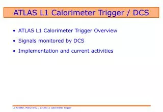
Current L1 Calorimeter trigger system • Counts of triggered objects above specified thresholds. • Regions of Interest (ROI) information on L1Accept.
Ideas on limited short-term topological upgrade The current L1Calo trigger system will remain mainly unchanged for next few years short-term upgrade backward compatible with the running system. Driven by MC simulations of L1 trigger rates at design luminosity in presence of pileup and necessary thresholds to keep them within a rate budget and impact on physics A promising solution is to collect additional RoI information (which is not currently used in the real-time data path), add topology algorithms based on relationships among triggered objects and thereby reduce the L1 rate The hardware components on which the system is built are about 5 to 7 years old and don’t allow much freedom for modifications: a limited modification of the algorithm processor firmware can be done in order to extract the necessary information; L1Calo crate backplane has advantage of higher bandwidth potential inherent in, but not used
Modifications required for limited upgrade Digitized ET Backplane Calorimetersignals(~7200) Cluster Processor 56 modules Merging 8 modules 0.10.1 PreProcessor 124 modules Analogue Sums Receivers New Topology Processor To CTP Backplane 0.20.2 Jet/Energy 32 modules Merging 4 modules L1 Muon Readout Driver 14 modules Readout Driver 6 modules Region-of-interest data Readoutdata • Firmware modification in processor modules • Increased data transfer rate over crate backplane (40 Mbit/s -> 160 Mbit/s) • New merging modules with processing capabilities • New Topology Processor (TP) – in a longer term
Current CMM (Common Merger Module) Processes the results from the CPMs or JEMs modules to produce results over the entire crate. Sends them to a ‘system’ CMMs in order to produce system-wide results sent on cables to the CTP. Responds to an L1A by providing data readout to DAQ and ROIB via the G-Links All CMMs are HW identical and capable of performing crate and system level operation. Several different firmware versions
New CMM (CMM++) functionalities • Backward compatibility - provide all the necessary functionality to replace a current CMM (electrical interfaces, programming model, data formats) • ROI information collection from upgraded CPM/JEM modules and transmission onwards to the Topology Processor (with or without internal processing) • Internal data processing capability - a desirable extra feature to provide some limited topological trigger functionality
CMM+ development scenario Design of the new hardware, based on the schematics of the current CMM – PCB with all present interfaces and optical links for the new topological processor) and one large FPGA replacing one/two current FPGAs Adaptation of the current CMM firmware to the new hardware in order to provide full backward compatibility and test with the current system Upgrade CPM/JEM and CMM++ modules firmware for the 40Mb/s to 160 Mb/s data transfer and a new data format (Optionally) CMM++ provides data in current format to CTP and data to the TP running in parallel with the current system but not connected to the CTP CMM++ supplies data to the TP connected to the CTP CMM++ can provides some limited TP functionality and topological experience while the TP is being built
Topology algorithms study Examples of possible topology algorithms that could be run based on L1 objects possible uses of each algorithm information needed to run the algorithm – local (quadrant) or global Overlap removal Use spatial overlap of RoIs of different types to remove double counting Requires only local information Vetoing on back-to-back jets Comparing the phi and eta of two objects Can be done locally with boundary information sharing Include jet energies in real time data path Estimate energy of overlapping e/tau object Mass or jet MET calculations What algorithms can be done with CMM++ only?
L1Calo trigger latency USA15 - latency measurements in the complete L1Calo system: Detailed breakdown in test rig: Part of total L1 latency! TCPP Receiver RPPP PPM CPM CMM “RMB” PPM CPM/JEM CMM T A B C D E F 0 30 52 72 73 85 1045 ? ? ? 960 (shall subtract 35+25 ns) 30 22 20 1 12 900 (36)
Available latency for the algorithms in L1 The maximum L1 latency was defined as 2500 ns (100 BCs) from collision to L1A arrival to detector FE pipeline How much spare latency left in detector FE pipeline LAr: depth – 144; latency – 95; spare – 10 BCs But dead time increase with the latency and trigge rate! Ongoing activity
JEM-CMM backplane data transfer Each CPM/JEM is sourcing 50 lines into two mergers at 40 Mbit/s Scope shots of JEM signals over the longest backplane track Backplane tested module was built: Data from all CPM/JEM modules 400 lines, individually deskewed Forwarded clock, sink terminated Eye > 3.7ns @ 160Mb/s Bit error rate tests on backplane data
CPM-CMM backplane data transfer CPM tests demonstrate160 Mbit/s with reasonable signal quality Test board alows to probe backplane signals in CMM slot Termination on CMM side improves signal quality, but increases dissipated power in CMM slot (a problem if done inside FPGA) Also tested signals with termination on source only
10 Gb ethernet-based optical link 10 Gbit Ethernet vs. FPGA I/O inexpensive, readily available components TLK3114SC Running links synchronously use LHC bunch gaps for link resynchronisation Run from TTC clock LMK03033CISQ clock conditioner Latency ~170 ns changes on reset can be fixed by comparing to other TTC signals to ~108 ns (not including propagation) Link board prototype
GOLD (Generic Opto Link Demonstrator) Explore optical links and new FPGAs Xilinx XC6VHX380T 640 I/O, 48 GTX, 24 GTH SNAP12 and Avago optolinks Optical backplane connectors ATCA form factor (8U x 280 mm) GOLD operated via the BLT (data source and control module) Optical control link extends VME functionality to GOLD Optical transmitter (SNAP12, up to 6.5 Gb/s) to be used as a data source Tests under way
CMM+ firmware development The CMM++ project includes a number of firmware sub-projects Porting the existing CMM firmware to the new CMM++ hardware preserving current CMM functionality in order to provide full backward compatibility with the CMM module, Creating the new firmware necessary to contend with new interfaces of CMM++ and FPGA, Porting and/or rewriting the CMM algorithms and creating the new algorithms necessary to add the topological functionality, The VHDL firmware framework will give the possibilities to work by several participants on different firmware sub-projects: verification environment - from Monte Carlo simulation via online simulation to VHDL test-benches, test-benches with set of models for CMM++ external systems based on Xilinx ISE design tool project settings: I/O configuration and placement Clock distribution and timing constraints
Porting the existing CMM firmware Aim: port “Jet” CMM firmware to new FPGA hardware: Use existing VHDL with minimal changes Update architecture-specific features Estimate I/O requirements Produce a realistic user constraint file (UCF) for Xilinx ISE tests Assign I/Os and clock signals to actual pins Implement in ISE to check actual resource use, clock speed Simulate to verify correct behaviour Ongoing activity
Project time-schedule 2010: Technical specification and preliminary design review CMM++ "real estate" (FPGA and links) and connectivity is fixed Input for the schematic capture and VHDL/FW framework 2011 – mid 1012: First prototype design (CMM drop in replacement) CMM++ schematics and PCB layout CMM firmware ported on CMM++ CMM++ (CMM configuration) test and integration into current system 2011 – 2012: parallel activities using VHDL/FW framework firmware for 160-MHz backplane transmission firmware for ribbon optical links firmware for ROD optical readout links algorithm development and CTP interface definition end 2012: Commissioning of the new CMM++ firmware hardware platform for current L1Calo trigger improvements