Download
1 / 31
310 likes | 527 Vues
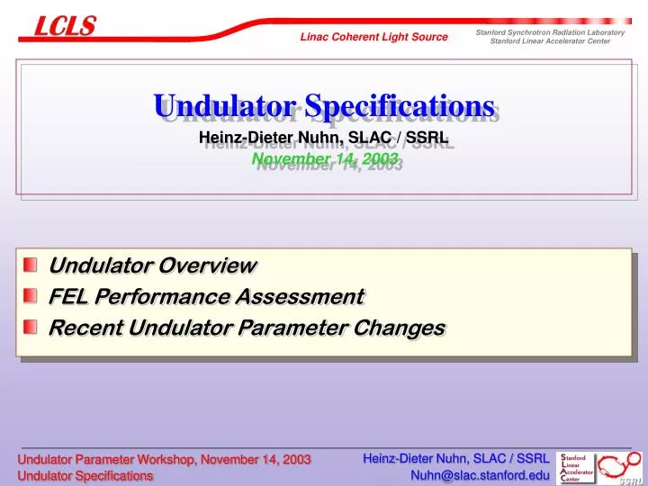
Undulator Specifications Heinz-Dieter Nuhn, SLAC / SSRL November 14, 2003. Undulator Overview FEL Performance Assessment Recent Undulator Parameter Changes. Near Hall. Far Hall. Undulator. Linac Coherent Light Source. LCLS Undulator Schematic (Regular Section). 3,410. 406. 863 mm.

E N D
Undulator SpecificationsHeinz-Dieter Nuhn, SLAC / SSRLNovember 14, 2003 • Undulator Overview • FEL Performance Assessment • Recent Undulator Parameter Changes Heinz-Dieter Nuhn, SLAC / SSRL
Near Hall Far Hall Undulator Linac Coherent Light Source Heinz-Dieter Nuhn, SLAC / SSRL
LCLS Undulator Schematic (Regular Section) 3,410 406 863 mm UNDULATOR 11,905 mm Horizontal Steering Coil Total Length 130,092 mm Vertical Steering Coil Beam Position Monitor X-Ray Diagnostics Quadrupoles Heinz-Dieter Nuhn, SLAC / SSRL
SASE FELs SASE FEL theory well developed and verified by simulations • FEL radiation starts from noise in spontaneous radiation • Transverse radiation electric field modulates the energy and bunches the electrons within an optical wavelength • Exponential build-up of radiation along undulator length Saturation Exponential Gain Regime Undulator Regime 1 % of X-Ray Pulse Electron BunchMicro-Bunching Heinz-Dieter Nuhn, SLAC / SSRL
Elegant Genesis / Ginger Parmela space-charge compression, wakes, CSR, … SASE FEL with wakes Expected Performance • Low charge cases are modeled in PARMELAafter the GTF results and then imported into ELEGANT/GENESIS for the transportthrough the LCLS beam line. • The simulations includes: • Space charge in the gun • Emittance compensation • Wakefield and CSR effects • Optimized beam transport (Jitter) • Spontaneous Undulator Radiation Start-To-End Simulations: All cases reach saturation Heinz-Dieter Nuhn, SLAC / SSRL
Workshop on Start-To-End Simulations Beam Dynamics Mini Workshop Future Light Sources Start-To-End Simulations for SASE FELs (S2E 2003) Chaired by John Galayda (SLAC) and Joerg Rossbach (DESY) Dates August 18 – 22, 2003 Location DESY-Zeuthen, Berlin, Germany Heinz-Dieter Nuhn, SLAC / SSRL
Comparison of GINGER/GENESIS resultsfor 1-nC LCLS “0-order” Case • Observations: • GENESIS shows very slightly longer gain length, later saturation but higher power • GINGER shows stronger post-saturation power oscillation (more deeply trapped particles?) • Method for choosing best K was slightly different for both codes Heinz-Dieter Nuhn, SLAC / SSRL
GINGER/GENESIS results for “0-order” 200-pC case • Observations: • Again, GENESIS shows slightly longer gain length, 10-m later saturation but 15% higher power • Again, GINGER shows deeper post-saturation power oscillation • Little sensitivity (2 m, 7%) in GINGER results to 8X particle number increase • Possible reasons for differences: • bugs • slight differences in initial e-beam properties (e.g. mismatch) • grid effects (e.g. outer boundary) • ??? Heinz-Dieter Nuhn, SLAC / SSRL
100 GW 1-nC LCLS: “1st-order” envelope reconstruction: max P(z) vs. slice time 100 GW GENESIS GINGER • Some quick observations: • Power suppressed in regions with high energy spread [-90:-70 fs] • GENESISshows ~2-3X greater power than GINGER for no-wake cases • For runs including wake fields, GINGER shows somewhat more peak power for the main body (but more localized in time) • Beam centroid wander may be important – better modeled byGENESIS Heinz-Dieter Nuhn, SLAC / SSRL
Tolerance Analysis: RON R. Dejus, N. Vinokurov Heinz-Dieter Nuhn, SLAC / SSRL
Undulator Performance Requirements (as of May 2003) 3.6350 6.5 Heinz-Dieter Nuhn, SLAC / SSRL
Trajectory Straightness Requirement • Preserve transverse overlap between beam and radiation • => Tolerance for betatron amplitude < 8 mm (beam radius dep.) • Avoid longitudinal phase shake between beam and radiation • => Tolerance for rms phase shake 10 degrees per module • => Equivalent tolerance for rms electron beam straightness 2 mm Heinz-Dieter Nuhn, SLAC / SSRL
Workshop on Undulator Parameters LCLS Undulator Parameter Workshop Chaired by Heinz-Dieter Nuhn (SLAC) Dates November 24, 2003 Location APS, Argonne, USA Heinz-Dieter Nuhn, SLAC / SSRL
Workshop Focus • Set Undulator Period • Reduction of maximum available linac energy • Undulator gap height increase • Longer break distances • Weaker FODO lattice Heinz-Dieter Nuhn, SLAC / SSRL
Adjusting Estimate of On-Axis Undulator Field • Halbach formula for hybrid undulator is used to estimate relation between gap/period and on-axis field • Measured prototype field 5.3% larger than estimated Heinz-Dieter Nuhn, SLAC / SSRL
Undulator Period • Present undulator period length of 3 cm is near optimum for shortest gain length • Change of undulator period length would require more man-power and time than available before next review • Undulator period length will be kept at lu = 3.0 cm Heinz-Dieter Nuhn, SLAC / SSRL
Maximum Available Linac Energy • 14.35 GeV has been nominal energy to reach 1.5 Å • Loss of available linac energy due to • Reduction of available linac sections (incl. Injector relocation) • Off-crest acceleration • New maximum energy set to 14.1 GeV to restore operational overhead • Requires change in K value Heinz-Dieter Nuhn, SLAC / SSRL
Undulator Gap Selection • Undulator gap height changes still possible • Present gap height: 6 mm • Gap height corrected for measured field: 6.35 mm • Parameter correction for reduced maximum energy • Larger gap gives access to short wavelength 1.0 Å More Room for Vacuum Chamber New Parameters Rejected Heinz-Dieter Nuhn, SLAC / SSRL
LCLS Undulator Large Gap / Low K Proposal Based on Chosen Parameters Proposed Undulator Length Safety Overhead Emittance Goal Emittance Achieved Heinz-Dieter Nuhn, SLAC / SSRL
New Break Lengths • Separations between undulator modules (breaks) designed to produce slippage by integer number of optical wavelength. • Break increments for adding slippage of 1 optical wavelength is DLB=lu (1+K2/2). DLB=23.7 cm (old); 22.8 cm (new) • Present design uses break pattern 1-1-2 which corresponds to the lengths sequence 18.7 cm – 18.7 cm – 42.1 cm • 18.7 cm gives not enough space for quads, BPMs, etc. Length needed > 30 cm 42.1 cm gives not enough space for x-ray diagnostics Length needed > 70 cm • New break pattern 2-2-4 corresponding to lengthsequence 40.6 cm – 40.6 cm – 86.3 cm Heinz-Dieter Nuhn, SLAC / SSRL
Weaker FODO Lattice • FODO Lattice had been designed for <bx,y>=18 m at 1.5 Å • Required gradient of 106-107 T/m for 5 cm long quads • New gradient set to 60 T/m to • Increase Saturation Power • Relax Beam-Based Alignment Tolerances • Saturation length only slightly increased • Average beta function at 1.5 Å is now <bx,y>=30 m • Focusing and defocusing magnets will be identical Heinz-Dieter Nuhn, SLAC / SSRL
LCLS Optimum b-Function at Short Wavelength 14.1 GeV Optimum Beta-Function New Beta-Function Heinz-Dieter Nuhn, SLAC / SSRL
LCLS Operating Points for 1 nC Bunch Charge (Old) LCLS Operating Point at 1.5 Å LCLS Operating Point at 15 Å Heinz-Dieter Nuhn, SLAC / SSRL
LCLS Operating Points for 1 nC Bunch Charge (New) Operating Point Operating Point LCLS Operating Point at 1.5 Å Heinz-Dieter Nuhn, SLAC / SSRL
LCLS Operating Points for 1 nC Bunch Charge (New) Operating Point Operating Point LCLS Operating Point at 15 Å Heinz-Dieter Nuhn, SLAC / SSRL
Beam Based Alignment Tolerances (Paul Emma) 2 100 100 0.04 4 0 Heinz-Dieter Nuhn, SLAC / SSRL
Summary of Nominal Undulator Design Changes OLD NEW Undulator Type planar hybrid planar hybrid Magnet Material NdFeB NdFeB Wiggle Plane horizontal horizontal Gap 6 6.5 mm Period Length 3.0 3.0 cm Peak On-Axis Field 1.325 1.298 T K 3.711 2.635 Module Length 3.41 3.41 m Number of Modules 33 33 Undulator Magnet Length 112.5 112.5 m Break Length 18.7-18.7-42.1 40.6-40.6-86.3 cm Total Device Length 121.8 130.2 m Heinz-Dieter Nuhn, SLAC / SSRL
Summary of Nominal Focusing Lattice Changes OLD NEW Lattice Type FODO FODO Magnet Type permanent permanent Nominal Magnet Length 5 5 cm QF Gradient 107 60 T/m QD Gradient -106 -60 T/m Average b Function at 1.5 Å 18.0 30 m Lowest Usable Energy 3.17 1.84 GeV Heinz-Dieter Nuhn, SLAC / SSRL
Summary of Electron Beam Parameters At 1.5 Å OLD NEW Electron Beam Energy 14.35 14.09 GeV g28082 27580 <b> 18.0 30.0 m rms beam radius 36 35 mm At 15 Å OLD NEW Electron Beam Energy 4.45 4.46 GeV g8880 8722 <b> 7.3 8.9 m rms beam radius 35 34 mm Heinz-Dieter Nuhn, SLAC / SSRL
Conclusions • Requirements for LCLS undulator are well established • LCLS undulator performance requirements are well understood • Risks have been assessed and undulator specifications address the risk • New parameter values have been chosen • Increase in undulator gap, • reduction in maximum electron beam energy, • longer break length, and • reduced quadrupole gradients • Benefits are • more room for vacuum chamber • more energy safety margin • more space for diagnostics components between undulator modules • increase of accessible wavelength range Heinz-Dieter Nuhn, SLAC / SSRL
End of Presentation Heinz-Dieter Nuhn, SLAC / SSRL