Download
1 / 51
640 likes | 2.04k Vues
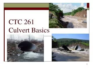
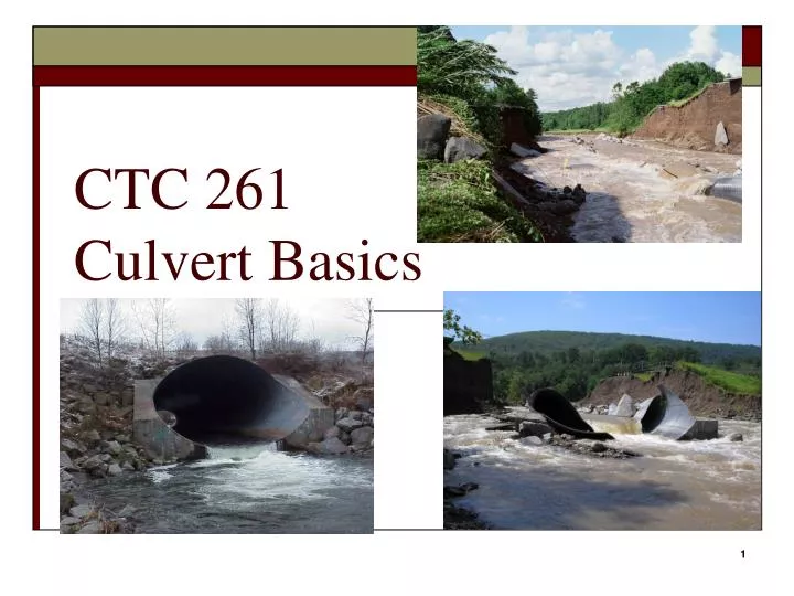
CTC 261 Culvert Basics. Objectives. Know the basic definition and types Know the basic types of culvert flow Know how to determine HW depth for inlet control . Hydraulic Design of Highway Culverts. USDOT/FHWA HDS 5 (highway design series #5) PDF available at:

E N D
Objectives • Know the basic definition and types • Know the basic types of culvert flow • Know how to determine HW depth for inlet control
Hydraulic Design of Highway Culverts • USDOT/FHWA • HDS 5 (highway design series #5) • PDF available at: http://isddc.dot.gov/OLPFiles/FHWA/012545.pdf • Most of the images in this powerpoint presentation were taken from HDS 5
Culvert • Hydraulically short conduit which conveys stream flow through a roadway embankment or past some other type of flow obstruction
Culvert Design • Conduit placed under a road to carry water from one side to the other • Designed to pass a design flow w/o overtopping the road
Culvert Flow • Complex • Pressure flow • Open channel flow • Combination • Variables • Slope • Pipe Diameter, Length and Roughness • Entrance Design • Exit Design
Culvert Materials-other • Corrugated Aluminum • Plastic • Polyethylene • Polyvinylchloride (PVC) • Stone
Culvert Hydraulics • Complete theoretical analysis is difficult • Flow conditions vary from culvert to culvert • Flow conditions vary over time • May flow full or partly full • Flow control-inlet or outlet • HDS approach is to analyze culvert for both types of flow control and design for minimum performance
Flow Conditions • Full Flow (pressure) – rare • Party Full (free surface) Flow • Subcritical • Critical • Supercritical • Evaluate flow regime via Froude # • Fr<1 Subcritical – Smooth flow, tranquil, low velocities • Fr=1 Critical Flow (point of minimum specific energy) • Fr>1 Supercritical – Swift, rapid, high velocities
Headwater (HW) • Depth of upstream water surface measured from invert ofculvert entrance • Should not exceed edge of shoulder elevation (account for freeboard) • Should not be so high as to cause flooding problems
Headwater (HWo) • Depth of upstream water surface measured from invert ofculvert outlet
Tailwater (TW) • Depth of downstream water surface measured from invert of culvert outlet • Usually determined by backwater calculations • Sometimes determined by normal depth calculations
Outlet Velocity • Outlet velocities are usually higher than in natural channel (constriction) • High velocities can cause streambed scour and bank erosion
Performance Curves • Plot of HW depth or elev. • versus flow rate • Inlet control curves • Outlet control curves
Economics • Risks • Decrease w/ larger culvert • Costs • Increase w/ larger culvert
Inlet Control • Inlet controls (or limits) the flow • Harder for flow to get through the entrance of the culvert than it is to flow through the remainder of the culvert
Inlet Control –A Barrel flow is partly full and supercritical (below critical depth) Critical depth occurs just d/s of culvert entrance Flow approaches normal depth @ outlet end
Inlet Control –B Flow d/s of inlet is supercritical (below critical depth) Hydraulic jump occurs in the barrel Note that submergence of outlet does not assure outlet control
Inlet Control –C Barrel flow is partly full and supercritical (below critical depth) Critical depth occurs just d/s of culvert entrance Flow approaches normal depth @ outlet end
Inlet Control –D (rare) Median drain provides ventilation/stable conditions Hydraulic jump occurs in the barrel Note that full-flow doesn’t occur even though inlet/outlet are submerged
Fall-Depressing the culvert entrance below the natural stream bed
Outlet Control • Outlet controls (or limits) the flow • Harder for flow to negotiate length of culvert than it is to get through the inlet (entrance)
Outlet Control –A (rare) Pressure Flow Full Flow Most culverts don’t operate this way Inlet/Outlet Submerged
Outlet Control –B Full Flow Inlet not fully submerged
Outlet Control –C Submerged inlet / unsubmerged outlet Requires high HW Outlet velocities usually high
Outlet Control –D (Typical) Inlet submerged Outlet unsubmerged Critical depth occurs just u/s of outlet Low TW
Outlet Control –E (typical) Flow is subcritical (laminar) Inlet and outlet are unsubmerged
Peak Flow Check Flow Hydrograph Storage routing Stream gage/regression/rational method/TR-55 Same as above Stream gage/ synthetic methods Data Requirements-Hydrology
Culvert Location Waterway Data Cross Sections Long. Slope Resistance Roadway Data Cross Section Profile Culvert Length Maps Field Surveys Roadway Plans Data RequirementsSite Data
Critical pts Surrounding bldgs Regulatory Constraints Arbitrary Constraints Roadway plans Maps/plans/photos Floodplain/flood insurance regs State or local regs Data RequirementsDesign Headwater
Inlet Hydraulics • Entrance Unsubmerged (weir) • Entrance Submerged (orifice) • Transition (in between; poorly defined)
Hydraulics-Energy Equation (EGL) • HW and TW depths and elevations • Velocity head (u/s & d/s) • Head losses • Friction loss through the barrel • Entrance/Exit losses • Bend/Junction/Grate losses
Definitions: Head (Friction) Losses • He-entrance loss • Hf-friction loss through the barrel • Ho-exit loss • Other potential losses due to bends, junctions and grates • Add losses up to calculated the total energy required to “push” water through the barrel
Definitions: Velocity • Vu-channel velocity upstream of the culvert • V-velocity through culvert barrel • Vd-channel velocity downstream of the culvert • Vu/Vd are often assumed to be minimal and left out of the equations
Roadway Topping • Water flows over the road and through the culvert • Flow over the road – broad crested weir • Usually occurs on sag curve • Represent sag w/ a single horizontal line • Represent sag w/ a series of lines
Culvert Design Form • Page 344 of HDS-5 • Calculate HW elev based on inlet/outlet control
Culvert Design Steps • Summarize all known data • Select a preliminary culvert material, shape, size and entrance type • Perform inlet control calculations • Perform outlet control calculations • If HW elevation is too high, then go back to step 2
Inlet Control • First step is to determine HW/D from charts • Chart 1B (Concrete Pipe-English) • Chart 2B (Corrugate Metal Pipe-English) • Chart 3B (Circular Pipe-Beveled Ring) • Chart 8B (Box Culverts) –D is box culvert Ht • Multiply by Diameter or Box Culvert Height to get HW
Dia=42” (3.5) • Q=120 cfs • Square edge with headwall • HW/D=2.5 • HW=8.8’ • Groove end with headwall • HW/D=2.1 • HW=7.4’ • Groove end projecting • HW/D=2.2 • HW=7.7’