Download
1 / 1
10 likes | 129 Vues
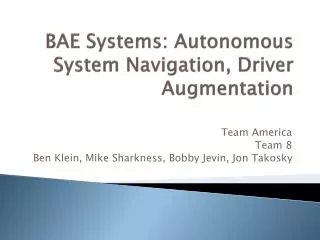
Driver Augmentation and Autonomous Navigation System Sponsored by EDSGN 100, Section 007 Group Members: Ryan Bradley, Matt Quigley, Mike Renard , Dan Bitner , Brandon Lehr. Problem Definition Needs

E N D
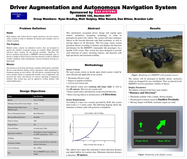
Driver Augmentation and Autonomous Navigation System Sponsored by EDSGN 100, Section 007 Group Members: Ryan Bradley, Matt Quigley, Mike Renard, Dan Bitner, Brandon Lehr Problem Definition Needs Both military and civilian drivers require proactive, not just reactive, safety systems in order to minimize the human and economic costs of vehicle accidents. The Problem Modern safety systems are primarily reactive; they are designed to protect the vehicle’s occupants during an accident. While generally effective, these systems do not prevent accidents. Therefore, the driver’s problem (specifically a HMMWV driver/commander pair) is that he is unable to detect fixed or moving obstacles in dark or difficult weather conditions while maintaining a convoy formation moving at a high speed. Mission Our mission is to develop and design a product which detects and helps drivers avoid obstacles during convoy operations, while maintaining a formation among several vehicles. We will deliver a detailed design for such a product which is economically feasible, easy to implement, and increases the safety and efficacy of convoys operating in dangerous territory. This system may also be applied to civilian markets with small modifications. Abstract This autonomous navigation device design will expand upon modern automotive navigation technology in order to preemptively protect the vehicle. The system will sense stationary objects in the forward direction with high resolution, as well as moving objects in all directions. This two-stage sensor system prioritizes threats according to distance and displays the direction and distance for the HMMWV commander (the passenger) via a durable LCD screen. This system has been designed to provide early detection of craters, incoming vehicles, and obstacles with high specificity and maximum usability. • Results • Figure: Rendering of a HMMWV with mounted sensors. • The sensors will be packaged in durable, plastic enclosures which are designed for easy installation. They are placed on the HMMWV roof for maximum visibility of threats. • Display Parameters • The display is based on the basic army mantra: • “Distance and Direction” • Maximum usability with a simple, abstract display. • Prioritization of threats based on Smallest Proximity. • Moving Targets will Blink; stationary targets are solid. • Figure: Rendering of the display screen. • Methodology • Sensor Criteria • We used certain criteria to decide upon which sensors would be most efficient and applicable in our system: • Maximum effective range • Degree of angular resolution • Cost of each sensor unit • The optimal system uses scanning mid range radaras well as two IR cameras.This two tier system will: • Detect small craters and obstacles in the forward-direction. • Detect moving objects in all directions, in 6 Directions. • Sensor Requirements • According to a base-case scenario provided by BAE, this system must avoid a 1×2 meter crater. The following diagram shows the minimum avoidance path with generous assumptions. • The authors have taken this minimum 6 meter detection distance and added buffers for reaction time. Minimum detection distance is therefore: 30 meters. Design Objectives