Download
1 / 28
2.85k likes | 7.91k Vues
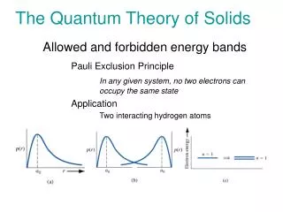
Band Theory of Solids. Learning Objective: Understanding the concept of energy bands in solids by applying the simple quantum mechanical concepts. Inter-atomic forces and Binding Energy in solids. For the very existence of solids

E N D
Band Theory of Solids Learning Objective: Understanding the concept of energy bands in solids by applying the simple quantum mechanical concepts.
Inter-atomic forces and Binding Energy in solids • For the very existence of solids • There must be attractive forces between atoms and molecules in a solid which keep them together; • There must be repulsive forces acting between the atoms as well, since large external pressures are required to compress a solid to any appropriate extent. Energy of attraction,Vattract = - α/rn…… (1) Energy of repulsion, Vrepuls = β/rm …… (2) Where α is attraction constant, β is repulsion constant, r is separation between the two atoms, m, n are constants ( characteristics of the molecule)
Inter-atomic forces and Binding Energy in solids The potential energy of the system, V(r) = Vattract + Vrepuls = …… (3) Therefore, the force between the two atoms as a function of r F(r) = - …… (4)
Interpretation of curves • At large separations, atoms do not interact with each other, i.e. V = 0. • As the separation is reduced, the atoms experience attractive forces due to +ve and –ve charges, and the potential energy decreases. • As the separation reduces to 1-2 atomic diameter, though the attractive forces become quite large but repulsive forces come into play, thus increasing the P.E. • At still lower interatomic separations, the repulsive forces become dominant due to +ve charges of the two nuclei (and also due to the interactions of the outer electrons of the two atoms). • Equilibrium is established only when F = 0. • Had there been no repulsive forces, the two atoms would collapse into each other due to large attractive forces at such short distances. • The bonding of atoms requires that repulsive forces are of shorter range than attractive forces.
Binding Energy in solids • At equilibrium, the net force is zero the point r0 in the F(r) curve. • Thus, Stable configuration of the system corresponds to the min. in V(r) (at r=r0). • The corresponding energy V(r0) is negative and is known as binding energy. • The dissociation energy is the energy required to separate the two atoms and is equal to - V(r0). D ~ 1 eV to a few eV • The min. in V(r) curve is possible only if m>n; Home Task: (F0 and >0 which gives m>n - check for yourself)
Binding Energy is Essentially Attractive F(r0) = ⃒= []= 0 Hence, …… (5) Therefore, V(r0) = = = If m>>n, V(r0) = the binding energy is attractive.
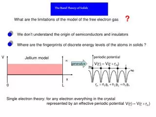
BASIS OF THE BAND THEORY OF SOLIDS • Some solids are good conductors of electricity, some are semiconductors, and others are insulators. • There is variation in resistivity with temperature. • The potential experienced by an electron during its motion through the crystal is periodic, instead of being constant or zero.
Origin of Energy-bands: Kronig-Penney model The model analyses the behavior of an electron of energy, E in a periodic square potential of period (a+b) such that V = 0 for 0 ≤ x ≤ a; and V = V0 for -b ≤ x ≤ 0; Also V(x) = V(x + (a+b)) The Schrodinger equation in the two regions can be written as and for 0 ≤ x ≤ a; …… (1) for -b ≤ x ≤ 0; …… (2)
Kronig-Penney model Kronig & Penny assumed that the energy of the electron, E<V0. The solution of equations (1) will be ψ = A Sin αx + B Cos αx ; where α2 = ……… (3) The solution of equations (2) will be ψ = C Sinhβx + D Coshβx ; where β2 = ……… (4) Solving eqns. (3) and (4) by using the boundary conditions for continuity of the wave function ψ and its first derivative dψ/dx, we get the following equation ……… (5)
Kronig-Penney model Consider the special case in which b→0 and V0→ such that V0 b remains finite; • The quantity V0 b is known as barrier strength. Under this consideration eqn (5) becomes ) = ) …….. (6) Or ) = ) …….. (7) Where Solutions of eqn. (7) are possible only when ) ≤ 1
Kronig-Penney model • Plot of P(Sinαa/αa) + Cos αa versus αa for P=3π/2, showing the allowed and forbidden energy regions • There are some values of α for which no valid k-value occurs. The corresponding E-values are forbidden (as E= )
E – k Diagram Discontinuities in the allowed energies occur at k-values given by k = ± nπ/a Therefore waves will be reflected at these values of k. These k-values give the Brillouin Zone boundaries. (n = 1 for first boundary) Hence a travelling wave (ψ = Ae±ikx) will suffer reflection at k = ± π/a And form stationary waves of the form ψ+ = Aeiπx/a + Ae-iπx/a = 2ACos πx/a ψ-= Aeiπx/a - Ae-iπx/a = 2iASin πx/a This will give the probability densities ρ+ = ⃓ψ+*ψ+⃓ = 4A2Cos2πx/a ==> ρ+ is maximum at x = ± na; ρ-= ⃓ ψ-*ψ- ⃓= 4A2Sin2πx/a ==> ρ-is maximum at x = ± (2n+1)a/2;
E – k Diagram • Thus ψ+ causes a collection of electrons in the vicinity of the ion cores (the nucei) thereby reducing the potential energy. • And ψ-causes a collection of electrons in betwen the ions,i.e. away from the ion cores, thereby increasing the potential energy.
E – k Diagram From the E-K diagram it is clear that electron has allowed energy values in the regions or zones extending from k= -π/a to k= +π/a (first Brillouin Zone), k= ±π/a to k= ±2π/a (2nd Brillouin Zone) And so on. E = h2k2/8π2m (Electron in a periodic potential) (Free electron)
Concept Of Effective Mass And Holes Effective mass of a particle is the mass it seems to carry in the semiclassical model of transport in a crystal. The deviation of the actual electron behaviour than free electron behaviour may be accounted simply by considering the electron to have effective mass m* rather than free electron mass m. The effective mass can also be negative or different than the free electron mass.
Concept Of Effective Mass And Holes Let an electron having effective mass m* is in a state k, and an external field ξ is applied. Therefore the force experienced by the electron, F = dp/dt = dk/dt= eξ as p = k …… (1) Also F = m*dv/dt = m* as v = vg =m* as E = ω = m* …… (2) From (1) & (2) eξ = m* (eξ/) = m* (eξ) m* = /
Concept Of Effective Mass And Holes Thus m* is a function of ‘k’ and depends on . The degree of freedom of an electron in periodic potential is given by fk = m/m* The concept of holes is introduced to facilitate the discussion of the transport in the "almost-full" valence band of a semiconductor. It is important to understand that one could deal with only electrons if one is willing to keep track of all the electrons in the "almost-full" valence band. After all, electrons are the only real particles available in a semiconductor. The concept of holes is introduced in semiconductors since it is easier to keep track of the missing electrons in an "almost-full" band, rather than keeping track of the actual electrons in that band. Holes are missing electrons. They behave as particles with the same properties as the electrons would have when occupying the same states except that they carry a positive charge.
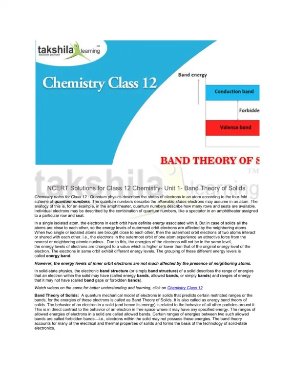
Classification of solids 1.Conductors (Metals) In case of conductors, there is no forbidden gap between the valence band and the conduction band. 2. Insulators A class of solids behaves as insulator if it satisfies the following two conditions: (i) it has even number of valence electrons per atom and (ii) the valence band and the conduction band are separated by a large energy gap compared with kT.
Classification of solids 3. Semiconductors In case of semiconductors, the energy band gap (forbidden gap) between the filled valence band and the empty conduction band is small as compared to the insulators and more as compared to the conductors. • Types of semiconductors • 1 .Intrinsic • 2 .Extrinsic
Hall Effect When a current carrying conductor (or semiconductor) is placed in a transverse magnetic field, a potential difference is developed across the conductor in the direction perpendicular to both current and magnetic field. This phenomenon is called Hall effect. The generated potential difference is known as Hall voltage. Hall Voltage and Hall Coefficient Let the charges are positive, and an electric field Ex is applied along x- direction, Hence the charges gain a drift velocity, vx. In absence of a magnetic field, VMN = 0 If a transverse magnetic field Bz is applied, charge q will experience a force (F1) towards negative y- direction given by Lorentz force.
Hall Voltage and Hall Coefficient F1 = q vxBz (towards N) Therefore, VN > VM ==> an upward electric field EH is created; And the force experienced by charge q due to EH, F2= q EH (towards M) At equilibrium, F2= F1 q EH = q vxBz==> EH = vxBz ….. (1) If ‘n’ be the carrier concentration, then current density is given as Jx=nqvx==> vx=Jx/nq….. (2)
Hall Voltage and Hall Coefficient From (1) and (2) EH =JxBz/nq….. (3) It is to be noted that EHαJx αBz Or, EH =RH JxBz, ….. (4) RH is the constant of proportionality and is known as the HALL COEFFICIENT. Comparing (3) and (4), we get RH = EH /JxBz = 1/nq….. (5) Potential difference between M & N is therefore, VH = EH b = JxBzb/nq Or, VH =IxBz/nqd ….. (6) If charge carriers are negative, Hall voltage and Hall coefficient will be negative.
Applications of Hall Effect • Determination of the sign of charge carriers. • Determination of carrier concentration. • Measurement of the mobility of charge carriers. • Measurement of the conductivity of a given specimen. • Hall effect can determine whether the given material is a metal, a semiconductor, or an insulator by determining the carrier concentration.
Fermi level and carrier concentration in semiconductors Intrinsic Semiconductor n-type Semiconductor p-typeSemiconductor
Fermi level and carrier concentration in intrinsic semiconductors If D(E) is the density of states with energy E, then concentration of conduction electrons will be …………. (1) Fermi Dirac probability function: Similarly concentration of holes in valence band, …………. (2) NC and NV are effective density of states: …………. (3)
Fermi level and carrier concentration in Intrinsic Semiconductors Carrier Concentration For intrinsic semiconductors, p = n = ni, Therefore ni= (np)1/2 Or ni = 2 (2πkT/h2)3/2 (me*mh*)3/4 e –(Ec-Ev)/2kT Fermi Energy As p = n, hence equating equations (1) and (2) and also using (3), we get EF = This suggests that EF ↑ as T ↑. If we consider me*= mh* , then EF=
Fermi level and carrier concentration in Extrinsic Semiconductors n-type semiconductors If ND is the donor concentration, then n ≈ Nd = EF(n) is the Fermi energy for the n- type semiconductor. EF(n) = EF(i) + kTln (Nd/ ni) p-type semiconductors If Nais the acceptor concentration, then p ≈ Na= EF(p) is the Fermi energy for the p- type semiconductor. EF(p) = EF(i) - kTln (Na/ ni)
References for some figures • http://www.google.co.in/imgres?sa=X&espv=210&es_sm=93&biw=1366&bih=624&tbm=isch&tbnid=bxgjrLeQ92wNSM%3A&imgrefurl=http%3A%2F%2Fparkafm.com%2Fmobile%2Fafmbg_4.php&docid=uKofG_OfJZZwuM&imgurl=http%3A%2F%2Fparkafm.com%2Fnew_img%2Fa%2Famb2.jpg&w=303&h=182&ei=7NknU5qwOsiMrQecsYGoDw&zoom=1&ved=0CGQQhBwwBg&iact=rc&dur=1820&page=1&start=0&ndsp=17 • https://lyle.smu.edu/ee/smuphotonics/Gain/CoursePresentationFall03/Effective_Mass_Theory_July25-03.pdf • https://www.google.co.in/url?sa=t&rct=j&q=&esrc=s&source=web&cd=3&cad=rja&uact=8&ved=0CDIQFjAC&url=http%3A%2F%2Fwww.egr.uh.edu%2FCourses%2FECE%2FECE6466%2FIC_Eng%2FChapter1_part2.ppt&ei=9EY2U5-QPImLrQfnrYHQBw&usg=AFQjCNE4PcM2s6yQAYOG7ptviM04Rhkw3A&bvm=bv.63808443,d.bmk