Download
1 / 66
660 likes | 759 Vues
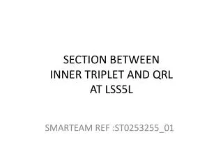
LHC IRQ Inner Triplet Review Q1, Q2, and Q3 Mechanics. T. Nicol April 24-25, 2007. Complete magnet assembly (Q3). Q1 supports at IP 5L. Brief history of notable design features. External heat exchanger (including the corrugated copper tube)

E N D
LHC IRQ Inner Triplet ReviewQ1, Q2, and Q3 Mechanics T. Nicol April 24-25, 2007
Brief history of notable design features • External heat exchanger (including the corrugated copper tube) • Driven by different Q1/Q3 and Q2 cold mass diameters from Fermilab and KEK. At the time of the initial design both labs were planning to build cold masses of each type. The external design allowed a magnet-independent heat exchanger design. • Spider support • Driven by the external heat exchanger which required a lot of radial space and precluded a suspension more like support posts used in the arc dipoles. • We sought to make a suspension system that was laterally stiff to preclude small oscillations due to ground motion and other influences. • Wanted to minimize warm to cold deviations. • Constant pressure to minimize static heat load lead to reduced thickness supports. • Welded cold mass bellows • Driven by the desire to make quick connections to the Fermilab Magnet Test Facility feedbox without welding and subsequent cutting. • Performance history at Fermilab has been good albeit with smaller diameters and lower operating pressures. • We learned later that allowed pressures from manufacturers only apply when the bellows are compressed flat and restrained.
Documentation • Engineering Notes • Technical Memos and Papers • Specifications • QA Documents • Drawings • Design Reviews • Meetings and Workshops Are all available at: http://tomato.fnal.gov/lhcirq/pressure_test_review/index.html
Materials • 304 stainless steel – Piping, flanges, etc. • Allowable stress: 138 MPa (20000 psi) • 304L stainless steel – Cold mass skins • Allowable stress: 115 MPa (16700 psi) • 6061-T6 aluminum – Shield shells and extrusions, pipe supports • Allowable stress: 59 MPa (8600 psi) • Carbon steel - Vacuum vessel • 248 MPa (36000 psi) min yield, Charpy toughness 21 J/cm2 min, 28 J/cm2 average over 3 tests (equivalent to L485MB) • G-11 CR – Supports • Allowable bending stress: 69 MPa (10000 psi) based on 139 MPa (20000 psi) ultimate • Allowable shear stress: 68 MPa (9800 psi) based on 131 MPa (19000 psi) ultimate • C932 bearing bronze – Support rods, cold mass adjusting screws
Loads considered • Shipping and handling loads. Vertical and lateral loads were thought to be the dominant loads driving the design of the suspension system. Axial shipping loads were always thought to be handled by external restraints. • Cooldown loads associated with change in diameter and length of the cold mass, piping, and thermal shield. • Pressure loading on the piping support system. Early design efforts focused more on individual magnet and cryostat elements rather than the system as a whole. Forces due to pressure asymmetries were underestimated and underappreciated. • Vacuum loading on the external support system. • Cold mass weight.
Q1 internal piping assembly FQ1-Q2
Q3 internal piping assembly FQ1-Q2 FQ1-DFBX
Path of forces Forces originate at the magnet interconnect from bellows spring forces and pressure induced axial forces… …they act on the internal piping and are transmitted to the cold mass through the pipe anchors… …then are transferred to the support structure through the anchor and slide mechanisms… …then to the vacuum vessel through the external support lugs… …and finally to the floor through the external jacks.
Q1 and Q3 forces Bellows forces, Fb, are due to pressure and mechanical compression and extension
Q1 pipe support weldment proposed modification See Q1 Pipe Anchor Stress Analysis – T. Page, April 19, 2007 Modified pipe anchor stresses Bracket to cold mass weld stress: 9121 psi (63 MPa) Elbow to end dome weld stress: 9430 psi (65 MPa) As designed pipe anchor stresses Bracket to cold mass weld stress: 41797 psi (288 MPa) Elbow to end dome weld stress: 17383 psi (120 MPa)
Q2 internal piping assembly FQ1-Q2 FQ2-Q3
Path of forces Forces originate at the magnet interconnect from bellows spring forces and pressure induced axial forces… …they act on the internal piping and are transmitted to the cold mass through the pipe anchors… …then are transferred to the support structure through the anchor and slide mechanisms… …then to the vacuum vessel through the external support lugs… …and finally to the floor through the external jacks.
Q2 forces Bellows forces, Fb, are due to pressure and mechanical compression and extension
Q2 pipe support shear stresses (Forces due to bellows installation forces at one end only.)
Summary of items tested • Heat exchanger performance extensively tested in full-scale prototypehttp://tdserver1.fnal.gov/nicol/lhc_irq_cryostat/ch_darve/public/publi/CEC_HXTU.pdf • Corrugated tube test. • Two supports tested to simulate lateral, vertical, and cooldown loadshttp://lss.fnal.gov/archive/1999/tm/TM-2093.pdf • Slide material testshttp://tdserver1.fnal.gov/nicol/lhc_irq_cryostat/ch_darve/Smt/TD-01-060_smt.pdf • Shipping and handling test • Bellows tests • Cooldown and shield line bellows tested to 25 bar – result lead to redesign of all bellows except for cold mass bellows • Cold mass bellows tested to 25 bar – result lead to supplemental squirm protection incorporated into bellows restraints • Warm fit-up at CERN in building 181