Download
1 / 56
560 likes | 735 Vues
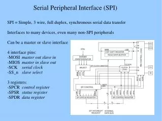
SPI - Serial Peripheral Interface. Pour aller lire le CAN et écrire dans le CNA. Schéma bloc. Chronogrammes. Mode 0. Mode 1. Chronogrammes. Mode 2. Mode 3. Chronogramme d’une transaction. Chronogramme d’une transaction. Registre des modes du SPI. Exemple initialisation du SPI.

E N D
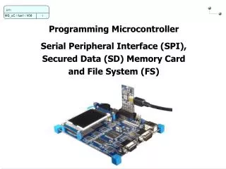
SPI - Serial Peripheral Interface Pour aller lire le CAN et écrire dans le CNA
Chronogrammes Mode 0 Mode 1
Chronogrammes Mode 2 Mode 3
Configuration du SPI • 1) Associer les broches au SPI: • Exemple SPI #1: • PIO_Configure(pinsSPI1, PIO_LISTSIZE(pinsSPI1));
Configuration du SPI • 2) Configuration des registres SPI_CR et SPI_MR: • Structure: • config = (AT91C_SPI_DLYBCS & (0 << 24)) | • (AT91C_SPI_PCS & (0xE << 16)) | • (AT91C_SPI_LLB & (0 << 7)) | • (AT91C_SPI_MODFDIS & (1 << 4)) | • (AT91C_SPI_PCSDEC & (0 << 2)) | • (AT91C_SPI_PS & (1 << 1)) | • (AT91C_SPI_MSTR & (1 << 0)); • SPI_Configure(AT91C_BASE_SPI1, AT91C_ID_SPI1, config);
Configuration du SPI • 2) Configuration des registres SPI_CR et SPI_MR : • Structure: • config = (AT91C_SPI_DLYBCS & (0 << 24)) | • (AT91C_SPI_PCS & (0xE << 16)) | • (AT91C_SPI_LLB & (0 << 7)) | • (AT91C_SPI_MODFDIS & (1 << 4)) | • (AT91C_SPI_PCSDEC & (0 << 2)) | • (AT91C_SPI_PS & (1 << 1)) | • (AT91C_SPI_MSTR & (1 << 0)); • SPI_Configure(AT91C_BASE_SPI1, AT91C_ID_SPI1, config); Délais entre « chip select » « Chip select » périphérique « Local loopback » Détection de fautes Décodage périphérique Sélection périphérique comm. Maitre ou esclave
Configuration du SPI • 2) Configuration du registre SPI_CSR3: • Structure: • config = (AT91C_SPI_DLYBCT & (0x01 << 24)) | • (AT91C_SPI_DLYBS & (0x01 << 16)) | • (AT91C_SPI_SCBR & (0x10 << 8)) | • (AT91C_SPI_BITS & (AT91C_SPI_BITS_16)) | • (AT91C_SPI_CSAAT & (0x0 << 3)) | • (AT91C_SPI_NCPHA & (0x0 << 1)) | • (AT91C_SPI_CPOL & (0x1 << 0)); • SPI_ConfigureNPCS(AT91C_BASE_SPI1, 3, config);
Configuration du SPI • 2) Configuration du registre SPI_CSR3 : • Structure: • config = (AT91C_SPI_DLYBCT & (0x01 << 24)) | • (AT91C_SPI_DLYBS & (0x01 << 16)) | • (AT91C_SPI_SCBR & (0x10 << 8)) | • (AT91C_SPI_BITS & (AT91C_SPI_BITS_16)) | • (AT91C_SPI_CSAAT & (0x0 << 3)) | • (AT91C_SPI_NCPHA & (0x0 << 1)) | • (AT91C_SPI_CPOL & (0x1 << 0)); • SPI_ConfigureNPCS(AT91C_BASE_SPI1, 3, config); Délai entre 2 transactions Délai avant SPCK Vitesse communication Taille du transfert (16 bits) Chip select actif après trans. ? Phase de l’horloge Polarité de l’horloge du SPI CNA
Configuration du SPI • 2b) Configuration du registre SPI_CSR2 : • … • SPI_ConfigureNPCS(AT91C_BASE_SPI1, 2, config); • 3) Activation du SPI: • Directement (pour le SPI #1): • SPI_Enable(AT91C_BASE_SPI1); • Tout cela peut se regrouper dans une fonction que nous pouvons nommer: • voidinitSPI(void){ • … • } CAN
Configuration broches MAX5322 Déclaration variables SetupDAC() Board.h
Suite Broche LDAC mise à 1 Broche CLR mise à 1 Broche UNI/BIP A mise à 0 Broche UNI/BIP B mise à 1 Broche SHDN mise à 1
Transactions du SPI avec le CNA • Initialisation du CNA • SPI_Write(AT91C_BASE_SPI1, 3, 0xE000); • SPI_Read(AT91C_BASE_SPI1); • Wait(1000); • SPI_Write(AT91C_BASE_SPI1, 3, (0x4000 | 0x07FF)); • SPI_Read(AT91C_BASE_SPI1); Activations des canaux du CNA 0 volt Canal A – DAC_OUT
Transactions du SPI avec le CNA • Initialisation du CNA • SPI_Write(AT91C_BASE_SPI1, 3, 0xE000); • SPI_Read(AT91C_BASE_SPI1); • Wait(1000); • SPI_Write(AT91C_BASE_SPI1, 3, (0x4000 | 0x07FF)); • SPI_Read(AT91C_BASE_SPI1); • SPI_Write(AT91C_BASE_SPI1, 3, (0x5000 | 0x0000)); • SPI_Read(AT91C_BASE_SPI1); Activations des canaux du CNA 0 volt Canal A – DAC_OUT 0 volt Canal B - VSHIFT