Download
1 / 13
130 likes | 298 Vues
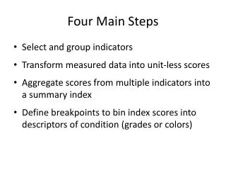
Main Steps of Beam Bending Analysis. Step 1 – Find Reactions at External Supports Free Body Diagram (FBD) of Entire Beam Equations of Force and Moment Equilibrium (3 in 2D) Step 2 – Shear and Bending Moment Diagrams Cutting Plane and FBD of Part of the Beam

E N D
Main Steps of Beam Bending Analysis • Step 1 – Find Reactions at External Supports • Free Body Diagram (FBD) of Entire Beam • Equations of Force and Moment Equilibrium (3 in 2D) • Step 2 – Shear and Bending Moment Diagrams • Cutting Plane and FBD of Part of the Beam • Use Equilibrium Eqs. to Express Internal Forces in Terms of Position Variable, “x” • Step 3 – Stress Distributions at Critical Sections • Linear Distribution of Bending (Normal) Stresses • Transverse Shear Stress Distribution in Terms of “Area Moment”
Pure Bending of Straight Symmetrical Beams • Linear bending stress distribution, and no shear stress (Fig. 4.3) • Neutral axis passes through centroid of cross-section • Section modulus, Z=I/c, used for the case when the neutral axis is also a symmetry axis for the cross-section • Table 4.2 for properties of plane sections • Restrictions to straight, homogeneous beams loaded in elastic range and cutting planes sufficiently far from discontinuities
Bending of Straight Symmetrical Beams Under Transverse Forces • Any cut cross-section loaded by two types of stresses (if no torsion occurs): • Bending stress as in case of pure bending • Transverse shear stresses • Direct and transverse shear stress • Direct average shear stress in pin and clevis joint (Fig. 4.4) is smaller than maximum stress • Non-linear distributions are caused in reality by stiffnesses and fits between mating members, etc.
Transverse Shear Stress Equations • Bending of laminated beam explains existence of transverse shear (Fig. 4.5) • Beam loaded in a vertical plane of symmetry • Elemental slab in equilibrium under differential bending and shear forces (Fig. 4.6) • Derived equation valid for any cross-sectional shape • Expressed in terms of “moment of area” about neutral axis, leading to the “area moment” method for calculating transverse shearing stresses • Irregular cross-sections can be divided into regular parts (4-25)