Download

1 / 33
350 likes | 460 Vues
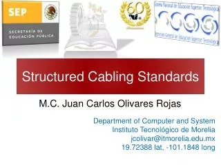
Cabling Technology and Standards. Networks. Data Communication Transfer of digital data between between 2 or more remotely attached autonomous systems in a reliable and understandable manner. Networks.

E N D
Networks • Data Communication • Transfer of digital data between between 2 or more remotely attached autonomous systems in a reliable and understandable manner
Networks • Network – data communication between 2 or more devices with the ability to access shared resources • LAN - local area network • WAN - wide area network
Networks Topologies Bus Ring Star
Networks Components • Hubs • Switches • Routers
Networks Components (Cont.) Hub connects multiple devices on same network via individual dedicated cable runs (star topology) Switch provides a dedicated communication channel between network devices
Networks Components (Cont.) • Router connects between entities residing on different networks
Common Abbreviations ACR - Attenuation to Cross-Talk Ratio P.ACR - Power Sum Attenuation to Cross-Talk Ratio BER - Bit Error Rate FEXT - Far End Cross-Talk NEXT - Near End Cross-Talk P.S. NEXT - Power Sum Near End Cross-Talk ELFEXT - Equal Level Far End Cross-Talk P.S. ELFEXT - Power Sum Equal Level Far End Cross-Talk STP - Shielded Twisted Pair TSB - Telecommunications Systems Bulletin UTP - Unshielded Twisted Pair Alien XT - Alien Cross Talk
Standards Organizations • EIA/TIA (USA) • Electrical/Telecommunication Industries Association • ANSI • American National Standards Institute • ISO/IEC • International Organization for Standardization • International Electrotechnical Commission • CENELC • European Committee for Electrotechnical Standardization • IEEE • Institute of Electrical and Electronic Engineers
World Structured Cabling Standards • ANSI/TIA/EIA-568-B.1 and B.2ratified in 2001, CAT5 / CAT5E • ANSI/TIA/EIA-568-B.2-1ratified in 2002, CAT6 • ANSI/TIA/EIA-568-B.2-10 finalized May 2008, CAT6a • ISO/IEC 2nd edition generic cabling standard 11801 ratified in 2002 • CENELEC generic cabling standard EN 50173-1ratified in 2002
Standards HistoryANSI / TIA / EIA-568 • ANSI/EIA/TIA 568 published in 1991 The 1st Commercial Building Telecommunications Wiring Standard The original document, together with TSB-36 & TSB-40 specified the basic transmission requirements of Category 3, 4 & 5 • ANSI/EIA/TIA 568A published in 1995Recognized Cables for Horizontal Cabling: 4 pair 100 UTP cables (including S/UTP) 2 pair 150 STP cables (IBM TYPE-1A) 2 fiber 62.5/125µ and 50/125µ fiber-optic cable
ANSI/TIA/EIA-568-B series • ANSI/TIA/EIA-568-B.1General Infrastructure requirements Copper and Fiber • ANSI/TIA/EIA-568-B.2Copper requirements Cat3, Cat5, Cat5E • ANSI/TIA/EIA-568-B.3Fiber requirements
ANSI/TIA/EIA-568-B-1 seriesGeneral Requirements • B-1.1 Minimum 4 pair UTP and ScTP patch cable bend radius • B-1.2 Bonding and Grounding • B-1.3 Supportable distances and Channel Attenuation for F/O applications by Fiber type • B-1.4 Recognition of CAT6 and 850 nm Laser-Optimized 50/125 µm MM F/O cabling • B-1.5 Cabling for Telecommunication Enclosures • B-1.6 PoE (Power Over Ethernet) • B-1.7 F/O connectivity Methods for Polarity
ANSI/TIA/EIA-568-B-2 seriesCopper • B-2.1 Category 6 specifications • B-2.2 Balanced Twisted-Pair Cabling Components • B-2.3 IL & RL Pass/Fail Determination • B-2.4 Solderless Connection Reliability Requirements for Copper Connecting Hardware • B-2.5 Corrections to TIA/EIA-568-B.2 • B-2.6 Cat 6 Related Component Test Procedures • B-2.7 Reliability Specification Requirements for Copper Connecting Hardware • B-2.8 Additional Component Req. for DTE Power • B-2.9 Additional Cat 6 Balance Requirements & Measurement Procedures • B-2.10 Augmented Cat 6 Cabling (10G)) • B-2.11 increased UTP and ScTP Cable Diameter
ANSI/TIA/EIA568-B-3 seriesFiber • B-3.1 Laser Optimized (OM-3) MM – 10 Gigabit • TSB 140 – Additional Guidelines for Field-Testing Length, Loss and Polarity of Optical Fiber Cabling Systems
CELENEC EN 50173-1 Series • EN 50173-1 General Requirements • EN 50173-2 Office (Commercial) Premises • EN 50173-3 Industrial Premises • EN 50173-4 Residential Premises • EN 50173-5 Data Centers
Link & Channel definitions Commercial Building Telecommunications Cabling Standard Link - The transmission between any two interfaces of generic cabling without equipment & work area cables (where an optional transition connection is allowed) Maximum Link length is 90 Mtrs Channel - The end-to-end transmission path connecting any two pieces of application specific equipment with equipment & work area cables Maximum Channel length is 100 Mtrs
CAT5 100 MHz Testing Link Performance of UTP cables in horizontal cabling Field test parameters: • Wire Map • Length • Attenuation • Near-End Cross Talk (NEXT) • Characteristic Impedance is not tested
CAT5E-100 MHz - TestingCAT6-250 MHz - TestingCAT6a-500 MHz - Testing CAT5E, CAT6, CAT6a Attenuation NEXT Powersum NEXT Wire Map Length ELFEXT Powersum ELFEXT Return Loss Delay Delay Skew
Categories and Classes • Category-specification for components – cables, patch panels, communication outlets • Class- specification for system application on full channel • CAT5 / Class D • CAT6 / Class E • CAT6a / New Class E • CAT7 / Class F • CAT8 / Class G
Categories -Summary • CAT3 – 10 Mbit, 16 MHz • CAT4 – 16 Mbit, 20 MHz • CAT5 – 10/100 Mbit, 100 MHz • CAT5E – 10/100/1000 Mbit, 100 MHz • CAT6 – 10/100/1000 Mbit + 10Gbit 55m channel, (STP), 250 MHz • CAT6A – 10/100/1000 Mbit + 10Gbit UTP and STP, 500 MHz • CAT7 – 10/100/1000 Mbit + 10Gbit, 600 MHz) • CAT7A – STP, Tera connector, 1 GHz • CAT8 – SOHO, 1200 MHz, 50m channel
Classes - Summary • A – 100 kHz (voice) • B – 1 MHz (ISDN…) • C – 16 MHz (Token Ring…) • D – 100 MHz (fast Ethernet, Gigabit Eternet) • E – 200 MHz usage / 250 MHz testing • F – 600 MHz usage / 750 MHz testing • G – 1200 MHz usage / 1500 MHz testing
CategoriesandProtocols • 10BaseT • 100BaseT (4 pairs CAT4) • 100BaseTX (2 pairs CAT5 – pins 1,2 and 3,6) • 1000BaseT (4 pairs CAT5E full duplex) • 1000BaseTX (4 pairs CAT6 – 2 pairs Txand 2 pairs Rx) • 10GBaseT (4 pairs CAT7 full duplex) • Maximumchannel length 100m
Category 6 • Standard ratified in 2002 • Bandwidth 250 MHz • 1GBit Ethernet applications • Protocol running 1000BaseTx • Full UTP/STP solutions
Category 6a • Standard ratified in 2008 • Augmented CAT6 • Channel up to 100 m • Bandwidth 500 MHz • UTP and STP solutions • New cable design (Horizontal and patch cords) • Issues with Alien CrossTalk (AXT)
Category 7 CAT7 – draft stage • Addressing broadband applications such as Video • Standadized by ISO/IEC and Cenelec (EN) • Bandwidth 600 MHz • STP solution only • Proposed connectors • Siemon Tera – not compatible with RJ45 • Nexans GG45
Category 7 Connectors NEXANS - GG45 Jack and GP45 Plug The Siemon Company - Tera™ • New connector design • Two compliant interface designs currently exist • Very little is installed, or projected to be installed, over the next two years
IEEE 802.3an - 10GBaseT • Bandwidth 500 MHz • Can run on CAT6 systemsbut limited to 55m channel– IEEE saysthis is sufficient for 70% of 10Gbit installationswhich are in Data Centers • On CAT6a systems full 100m channel
Futuredevelopments (Increasing need for speed) IEEE 802.3 HSSG (higher speed study group) • 40/100 Gb/s (design goal) • Sm optical fibre, 10 km • MM optical fibre (OM3), 100 m • Copper, 10 m, STP cabling eight pairs Development plan with schedule for standard in November 2009
Wire Map Standards Pair 1 (Blue) Pair 1 (Blue) 568A 568B Pair 2 (Orange) Pair 3 (Green) Pair 4 (Brown) Pair 2 (Orange) Pair 4 (Brown) Pair 3 (Green)
Official Certifications • RiT products are officially approved by thefollowing institutions: • DELTA (Denmark) • ETL (USA) • SEV (Switzerland)