Download
1 / 6
100 likes | 578 Vues
Interference Figures. IN THIS LECTURE Interference Figures Taking Interference Figures Uniaxial Interference Figures Optic Axis Interference Figure Off-Centre Figure Optic Normal or Flash Figure Determining Optic Sign. Interference Figures.

E N D
Interference Figures IN THIS LECTURE • Interference Figures • Taking Interference Figures • Uniaxial Interference Figures • Optic Axis Interference Figure • Off-Centre Figure • Optic Normal or Flash Figure • Determining Optic Sign
Interference Figures • An interference figure allows the rapid determination of optical character, ie whether the mineral is uniaxial or biaxial, and to determine the optic sign. If the mineral is biaxial, the 2V may also be measured. • To view an interference figure • Focus on a single grain with the high-power objective lens • Flip in the auxiliary condensing lens • Refocus if needed and open the aperture diaphragm • Insert the upper polariser • Insert the bertrand lens • An interference figure may also be observed without the bertrand lens by removing the ocular and looking directly down the microscope tube.
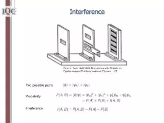
Interference Figures • The interference figure is formed near the top surface of the objective lens and consists of a pattern of interference colors called isochromes on which dark bands called isogyres are superimposed. The nature of the interference figure and its behaviour as the stage is rotated depends on the orientation of the mineral grain and whether the mineral is uniaxial or biaxial.
Formation of the Melatope, and Isochromes • The point in the centre where the isogyres cross is called the melatope. • It marks the point of emergence of the optic axis. • The presence of a single melatope indicates that the mineral is uniaxial. Biaxial minerals have by definition two melatope. • Light following the optic axis is not split into two rays and exits the mineral with zero retardation and hence looks black. • Isochromes form by light rays that are split into two directions (because they are not parallel to the optic axis). • With increasing angle away from the optic axis, the retardation becomes greater and hence the interference colors increase. • Because optic properties are symmetric about the optic axis, rings of equal retardation and interference color are formed about the melatope.
Formation of Isogyres • Isogyres form where vibration directions in the interference figures are N-S and E-W and are hence areas of extinction. • Ordinary (w) rays vibrate parallel to lines of latitude and extraordinary (e’) rays vibrate parallel to lines of longitude on the indicatrix. • These vibration directions are carried up into the indicatrix • Extraordinary (e’) rays vibrate along radial lines symmetric about the melatope and ordinary (w) rays vibrate tangent to the circular isochromes. • The isogyres become wider and have more diffuse edges further from the melatope.