Download
1 / 13
130 likes | 191 Vues
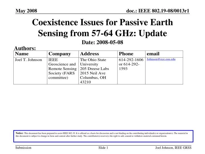
Coexistence Issues for Passive Earth Sensing from 57-64 GHz: Update. Authors:. Date: 2008-05-08.

E N D
Coexistence Issues for Passive Earth Sensing from 57-64 GHz: Update Authors: Date: 2008-05-08 Notice:This document has been prepared to assist IEEE 802.19. It is offered as a basis for discussion and is not binding on the contributing individual(s) or organization(s). The material in this document is subject to change in form and content after further study. The contributor(s) reserve(s) the right to add, amend or withdraw material contained herein. Joel Johnson, IEEE GRSS
Abstract Previous slides IEEE 802.19-08/0013r0 documented the potential for co-existence issues between 802 plans 57-64 GHz and Earth Observing Passive Microwave sensors Analysis updated here to correct an error, to reflect comments on previous presentation, and to provide more information on specific sensors currently in orbit Joel Johnson, IEEE GRSS
Passive Microwave Observations • Passive microwave systems (microwave radiometers) have a long history of providing vital meteorological measurements • Systems are receive-only, and observe naturally emitted thermal noise from the Earth’s environment • Frequencies near the 60 GHz oxygen absorption line are critical for obtaining atmospheric temperature profiles; this is done by using several radiometer frequencies at varying locations along the line • Current and future US and international satellites are using these frequencies, including the AMSU and SSMI/S sensors on-board several defense meteorological satellites as well as the future ATMS • ITU regulations recognize the importance of these frequencies for the Earth observations by providing the EESS (passive) service with a shared primary allocation from 57-59.3 GHz Joel Johnson, IEEE GRSS
ITU RS.1029-2 • ITU recommendation RS.1029-2 also addresses the EESS service from 57-59.3 GHz • Sets a received power limit of -169 dBw not to be exceeded either 0.01% of the time or area • this is 0.01K in a 100 MHz radiometer bandwidth • Scan mode: N=Nadiral, L=Limb Joel Johnson, IEEE GRSS
Previous Co-Existence Analysis • Used Friis formula as starting point for received power Pr: • Requires knowledge of: • transmitted power (Pt), antenna gain of transmitter in direction of radiometer (Gt), [radiometer antenna effective area (Aeff) in direction of transmitter, Range to radiometer (R)], atmospheric attenuation (exp(-tau)) • Recast in terms of an EIRP density equation for brightnessperturbation given radiometer bandwidth B and number of sources N in footprint of area A; k is Boltzmann’s constant Joel Johnson, IEEE GRSS
Equation in more convenient units • Rewrite in terms of the number of sources per square kilometer N’ and get rid of constants: - Q<1 is a scale factor to account for the fact that the satellite is in a transmitter antenna sidelobe - F<1 is a scale factor to account for the portion of the transmitter EIRP that lies within the radiometer bandwidth • CORRECT ERROR: previous final equation gave left hand side as 1 for 100 MHz and 10 mK, should be 1000 • CLARIFY: For systems observing at oblique angles, attenuation in dB is multiplied by the secant of the incidence angles, e.g. at 45 degrees attenuation in dB increases 41% Joel Johnson, IEEE GRSS
Zenith Atmospheric Attenuation • Compute using ITU P676-7 algorithms: Joel Johnson, IEEE GRSS
What are Q and F? • Information on expected transmit antenna properties as well as through wall-attenuation, scattering, etc. is required to model Q • Learned that transmit antennas are expected to be around 10 dBi gain last time, suggests that zenith sidelobes may not be extremely small • Presence of transmitters at higher altitudes (i.e. airborne) is a concern due to reduction in atmospheric attenuation • Information on radiometer bandwidths and transmitter modulation properties required to model F • Nominally would be B/(Bt) where Bt is the transmitter bandwidth if the transmitter produces a flat power spectral density (psd) • Will transmit psd be flat? What are expected variations in time? Radiometer integration times are ~msec scales so average up to ~msec is of interest Joel Johnson, IEEE GRSS
Current state of analysis • If we go ahead and assume a flat psd for transmitters we can get rid of F by using the transmit bandwidth on the RHS • If the transmit bandwidth is 2000 MHz and we use 10 mK, the left hand side is (2000)(10). • 42 dBm EIRP=16 Watts, 82 dBm EIRP=160 kW • Zenith atmospheric attenuation ~80 dB @ 57.3 GHz in Denver; about a factor of 30 times more at sea level • Need some guesses as to what Q and N’ are! Joel Johnson, IEEE GRSS
AMSU • The Advanced Microwave Sounding Unit-A (AMSU-A) is a 15-channel cross- track, stepped-line scanning, total power microwave radiometer • The instrument has an instantaneous field-of-view of 3.3° at the half-power points providing a nominal spatial resolution at nadir of 48 km (29.8 mi) • The antenna provides a cross-track scan, scanning ±48.3° from nadir with a total of 30 Earth fields-of-view per scan line • This instrument completes one scan every 8 seconds. • AMSU measures thermal noise in 26 frequency bands from 56.9 to 57.7 GHz, bandwidths from 3 to 330 MHz • Multiple AMSU’s currently in orbit, more planned for the future Joel Johnson, IEEE GRSS
SSMI/S • SSMI/S is a conical scanning multi-frequency radiometer observing at 53.1 degrees incidence angle • Main beam attenuation in dB 66.6% larger than nadiral • However any nadiral antenna sidelobes could be a concern • Includes channels from 57.1-57.5 and 63-63.6 GHz, as well as several near 60 GHz • Lower overall attenuation @ 63 GHz could be an issue (no allocation for EESS observations here) Joel Johnson, IEEE GRSS
Future instruments • The NPOESS system is slated to combine DoD and NOAA weather satellites into a single system in the next decade • ATMS: Similar to AMSU in most aspects • MIS: still under definition but likely somewhat similar to SSMI/S Joel Johnson, IEEE GRSS
Conclusion • Correction of error shows there is more lee-way than previously derived • However it is still not clear that interference will not occur • Need guesses regarding N’ and Q • Probably 42 dBm systems will have larger values of Q than 82 dBm systems • Properties of 82 dBm system antennas +scattering are important • More information at: • http://esl.eng.ohio-state.edu/~rstheory/57ghz/57ghz.html Joel Johnson, IEEE GRSS