Download

1 / 88
900 likes | 1.05k Vues
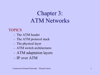
Chapter 9 ATM Networks. Why ATM? BISDN Reference Model ATM Layer ATM Adaptation Layer ATM Signaling PNNI Routing Classical IP over ATM. Chapter 9 ATM Networks. Why ATM?. The Integrated Services Vision. Initially telephone network all-analog Transmission & Switching

E N D
Chapter 9ATM Networks Why ATM? BISDN Reference Model ATM Layer ATM Adaptation Layer ATM Signaling PNNI Routing Classical IP over ATM
Chapter 9ATM Networks Why ATM?
The Integrated Services Vision • Initially telephone network all-analog • Transmission & Switching • Gradual transition to all-digital core • 1960’s: transmission in backbone became digital • 1970’s: switching became digital • Subscriber loop from customer to network remained analog • Integrated Services Vision: • Network should be digital end-to-end • Network should support all services: telephone, data, video • Three attempts at achieving Integrated Services Network • ISDN in 1980s • ATM/BISDN in 1990’s • Internet in 2000’s
Integrated Services Digital Network (ISDN) • ISDN: • Integrated access • to end-to-end digital communication services • through a standard set of user-to-network interfaces • Network consisted of separate networks for voice, data, signaling Basic rate interface (BRI): 2B+D Circuit- switched network B=64 kbps D=16 kbps Private channel- switched network BRI BRI Packet- switched networks PRI PRI Primary rate interface (PRI): 23B+D Signaling network
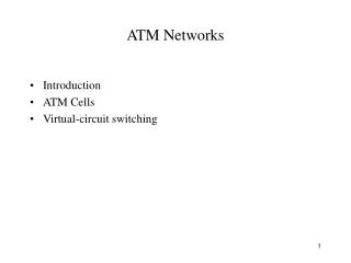
Broadband ISDN • BISDN: A single universal network that is flexible enough to provide all user services in a uniform manner • ISDN not enough: Needed 10s to 100s Mbps for LAN interconnect and for digital TV • Synchronous Transfer Mode (connections at nx64 kbps) was initial candidate for BISDN, but • Asynchronous Transfer Mode(ATM) chosen • Multiplexing & switching framework • connection-oriented virtual circuits • fixed-length packets, “cells”, with short headers
Benefits of ATM • Network infrastructure and management simplified by using a single transfer mode for the network • Expected to cover LAN, MAN, and WAN • Extensive bandwidth management capabilities • SONET-like grooming capabilities, but at arbitrary bandwidth granularities • ATM is not limited by speed or distance limitations • 50-600 Mbps the sweet spot for ATM • QoS attributes of ATM allow it to carry voice, data, and video thus making it suitable for an integrated services network.
48 bytes 5 bytes Network header User information local area network (LAN) multimedia terminal wireless interface ATM fibre backbone Wide Area Network (WAN) video server wireless interface data base supercomputer ATM Anticipated Scope • All information transferred by network that handles 53-byte cells • Scalable in terms of speed • Switched approach operates in LAN, MAN, or WAN
Voice Packet Video Voice Packet Video ATM Adaptation Layer ATM Adaptation Layer ATM Network ATM Networking
Voice AAL A/D s1 , s2 … cells Digital voice samples Video Compression … AAL A/D cells compressed frames picture frames Data AAL cells Bursty variable-length packets AAL converts Info into Cells
Cells Cells Cells Source Cells Switches Destination Cell-Switching – Virtual Circuit • Connection setup establishes virtual circuit by setting pointers in tables in path across network • All cells for a connection follow the same path • Abbreviated header identifies connection • Cells queue for transmission at ATM switches & multiplexers • Fixed and Variable bit rates possible, negotiated during call set-up • Delay and loss performance negotiated prior to connection setup
1 1 voice 67 Switch … video 67 2 N 25 75 video voice 5 25 32 1 32 67 3 data 39 32 3 39 video data 32 61 6 61 2 67 … … video 75 N N ATM Switching Switch carries out table translation and routing • ATM switches can be implemented using shared memory, • shared backplanes, or self-routing multi-stage fabrics
1 1 2 2 N N Multiplexing in ATM Switches • Packet traffic multiplexed onto input lines • Demultiplexed at input port • Forwarded to output port
ATM Support for Multiple QoS Levels VCs with different TDs & different QoS reqts • Call Admission Control based on Traffic Descriptors & QoS Reqts • Cell streams policed at User Network Interface • Cell Enqueueing Policy, Cell Transmission Scheduling, Flow Control • Generalized Processor Sharing, Weighted Fair Queueing, etc. • Multiplexing Gain • Cell Multiplexing implies Delay, Jitter, Loss
Chapter 9ATM Networks BISDN Reference Model
User Plane: transfer of user information; flow control; error recovery Control Plane: setting up, management, and release of connections Layer Management Plane: management of layer entities & OAM Plane Management: management of all the planes Management Planes Control Plane User Plane Plane Management Higher Layers Layer Management ATM Adaptation Layer ATM Layer Physical Layer BISDN Reference Model
Planes Explained • Three types of logical networks are involved in delivering communication services • User Network: transfers user information • Control (Signaling) Network: carries signaling messages to establish, maintain, terminate connections • Management Network: carries management information: monitoring information, alarms and usage statistics • A separate protocol stack, “plane”, is defined for each of these three networks
Higher Layers Higher Layers ATM Adaptation Layer (AAL) ATM Adaptation Layer (AAL) ATM Network Layer ATM Network Layer ATM Network Layer Physical Layer Physical Layer Physical Layer USER NETWORK USER ATM Layered Architecture
ATM Adaptation Layer standard interface to higher layers adaptation functions end-to-end between end systems segmentation into cells and reassembly ATM Layer Transfer of Cells Cell-Header Generation/Extraction VPI/VCI Translation Cell multiplexing/demultiplexing Flow and congestion control Physical Layer Cell stream / bit stream conversion Digital transmission Higher Layers ATM Adaptation Layer (AAL) ATM Network Layer Physical Layer ATM Layered Architecture
ATM Interfaces Private ATM network UNI: User-Network Interface NNI: Network-Network Interface B-ICI: Broadband Inter-carrier i/f Private UNI X X Private NNI Public ATM network A Public UNI X X X NNI Public UNI X Public ATM network B B-ICI X Public UNI X X
TC Sublayer: Cell Delineation Header Error Checking Cell Rate Decoupling (Insertion of Idle Cells) Specific to PMD PMD Sublayer: Line code Connectors Re-use of existing physical layer standards Transmission convergence sublayer Physical medium dependent sublayer The ATM Physical Layer
Private UNI Physical Layers UTP = Unshielded twisted pair STP = Shielded twisted pair MMF = Multimode fiber SMF = Single-mode pair
Chapter 9ATM Networks ATM Layer
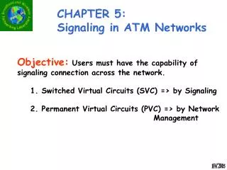
The ATM Layer • Concerned with sequenced transfer of cells across network connections • ATM Connections • Point-to-Point: unidirectional or bidirectional • Point-to-Multipoint: unidirectional • Permanent Virtual Connections (PVC): long-term connections to provision bandwidth between endpoints in an ATM network • Switched Virtual Connections (SVC): shorter-term connections established in response to customer requests
Virtual paths Virtual channels ATM Virtual Connections • Virtual Channel Connections: virtual circuit • Virtual Path Connections: bundle of virtual connections • ATM Header contains virtual connection information: • 8-bit Virtual Path Identifier • 16-bit Virtual Channel Identifier
Why 53 Bytes? • The effect of delay on packet voice influenced selection of cell size • The packetization delay grows with the cell size • @64kbps: packetization delay = cell size * 125 sec • If delay is too long, echo cancellation equipment needs to be introduced • Europe has short transmission lines and no echo cancellers so it proposed 32 byte payload • U.S. has long transmission lines and echo cancellers in place, so it proposed 64 byte payload • Compromise: 48 byte payload
GFC (4 bits) VPI (4 bits) VPI (4 bits) VCI (4 bits) ATM cell header VCI (8 bits) CLP (1 bit) VCI (4 bits) PT (3 bits) HEC (8 bits) Payload (48 bytes) The ATM Cell Virtual Path Identifier • 8-bits: 256 VC bundles Virtual Channel Identifier • 16 bits: 65,536 VCs/VP Payload Type Indicator • Bit 3: data vs. OAM cell • Bit 2: Congestion indication in data cells • Bit 1: Carried transparently end-to-end; Used in AAL5 Cell Loss Priority • if 1, cell can be discarded by network GFC-undefined UNI cells has GFC field NNI cells allocate these 4 bits to VPI; 4096 VPs
Header Error Check • The HEC only covers the 5 bytes of the header to protect against cell misdelivery • Since VPI/VCI changes at every switch, HEC must be recomputed • HEC used for cell delineation • Two modes: Header Error Detection / Correction • Generating Polynomial: g(x)=x8+ x2+ x+ 1 • The pattern 01010101 is XORed to r(x); keeps idle cells from having HEC=0 and preventing cell delineation • The pattern 01010101 is XORed to r(x) in received header prior to error checking
ATM Switch ATM Permanent Virtual Connections Operator at Network Control Center ATM Switch • Operator “manually” sets up VPI/VCI tables at switches and terminals • Long set-up time, long-lived connections
ATM Switch ATM Switched Virtual Connections ATM Switch • Terminals and switches use pre-defined VPI/VCI to setup connections dynamically, on-demand • Signalling protocol used to communicate with call-processing system
Traffic Contract • During connection setup the user and the network negotiate two sets of parameters for a connection • Traffic descriptor: the user specifies the traffic that it will expect the network to transfer on its behalf • QoS requirements: the user specifies the type of network performance that is required by its cells • Traffic Contract • The user is expected to conform to traffic descriptor • The network is expected to deliver on its QoS commitments
Quality of Service Parameters • Six QoS parameters are defined • Three are intrinsic to network performance and are not negotiated during connection setup: • Cell error ratio: fraction of delivered cells that contain bit errors • Cell mis-insertion ratio: average number of cells/second that are misdelivered • Severely errored cell block ratio: M or more out of N cells are lost, in error, or misdelivered
probability density of cell delay D0 Peak-to-Peak CDV Dmax Negotiable QoS Parameters • Cell Loss Ratio (CLR): fraction of cells that are lost • Determined by buffer priority • Cell Transfer Delay (CTD): negotiate “maximum delay” Dmax: 1-a of cells have delay less than Dmax • Determined by cell scheduling • Cell Delay Variation (CDV): Peak-to-Peak variation: Dmax-D0
Traffic Descriptors • Peak Cell Rate: rate in cells/second that a source is never allowed to exceed • Sustainable Cell Rate: average cell rate produced by the source over a long time interval • Maximum Burst Size: maximum number of consecutive cells that may be transmitted by a source at the peak cell rate (PCR) • Minimum Cell Rate: minimum average cell rate, in cells per second, that the source is always allowed to send • Cell Delay Variation Tolerance: cell delay variation that must be tolerated for in a given connection.
ATM Service Categories Cell transfer services provided by ATM Network VBR real-time VBR non-real-time ABR UBR CBR Cell Loss Rate specified unspecified Cell Transfer Delay specified unspecified Cell Delay Variation unspecified specified Traffic Descriptors PCR/CDVT SCR/BT PCR/CDVT & others PCR/CDVT PCR/CDVT Flow Control yes no no CBR = Constant Bit Rate VBR = Variable Bit Rate ABR = Available Bit Rate UBR = Unspecified Bit Rate PCR = Peak Cell Rate CDVT = Cell Delay Variation Tolerance SCR = Sustainable Cell Rate BT = Burst Tolerance
Multiplexing & QoS Guarantees • ATM provides per-connection QoS guarantees • Many cell flows are multiplexed onto a common stream, so how are guarantees delivered? • CBR: scheduler must ensure transmission opportunities are regularly available for each connection • Real-time VBR: expect some multiplexing gain from combining VBR flows; however need to meet delay and loss requirements • Non-real-time VBR: can attempt higher multiplexing gains, subject only to loss requirement • UBR: no guarantees, but excellent performance at light traffic • ABR: some degree of guarantee: low CLR if source responds to network feedback; MCR can be negotiated
Traffic Contract & Call Admission Control • Traffic contract: includes the ATM service category, the traffic descriptors, and the QoS requirements • Connection admission control (CAC) determines whether request for a connection should be accepted or rejected • Each switch in path must determine whether it can accommodate new flow and still meet commitments to existing flows; if yes, resources allocated • CAC is not standardized, each operator is free to select own procedures • Different degrees of overbooking possible to attain different multiplexing gains • Different types of tariffs for service offerings
Policing, Traffic Shaping, and Congestion Control • QoS guarantees are valid only if the user traffic conforms to the connection contract • Usage parameter control (UPC) is the process of enforcing the traffic agreement at the UNI • Generic Cell Rate Algorithm can be used for UPC; related to the leaky-bucket algorithm • Non-conforming cells can be tagged (CLP=1) or dropped • Traffic shaping can be used by source to ensure that its traffic complies to the connection contract • Token bucket can be used for shaping • Congestion control • CLP=1 cells are dropped first when congestion occurs • ABR connections must respond to congestion feedback information that is received from the network • These topics were discussed in Chapter 7
Chapter 9ATM Networks ATM Adaptation Layer
AAL: end-to-end protocol to adapt the cell transfer service provided by ATM network to the requirements of specific application classes Includes conversion to cells and back, and additional adaptation functions, e.g. timing recovery, reliable transfer ITU defined the following service classes B D Class A C End-to-End Timing required not required Bit Rate constant variable Connection Mode connection-oriented connectionless ATM Adaptation Layer Class A = circuit emulation Class B = variable bit-rate video Class C & D = packet transmission
Service Specific Convergence Sublayer Convergence Sublayer Common Part AAL Layer Segmentation and Reassembly Sublayer AAL Protocol Structure AAL has two sublayers: • Segmentation & Reassembly • Segments PDUs into cell payloads; Reassembles PDUs from received cell payloads • Convergence • Common Part: packet framing and error detection functions required by all AAL users • Specific Part: functions that depend on specific requirements of AAL user classes Higher Layers ATM
User data stream Higher layer … b1 b2 b3 Convergence sublayer CS PDUs 47 47 47 SAR PDUs SAR sublayer H H H 1 47 1 47 1 47 ATM Cells H H H ATM layer 5 48 5 48 5 48 AAL1 • Provides constant bit rate transfer
Convergence Sublayer: Adaptation to cell-delay variation, constant bit rate delivery AAL-SDUs Detection of lost or out-of-sequence cells Source clock recovery Forward error correction on user data Forward error correction on Sequence Number (SN) 1-bit CS to indicate pointer (used for partially-filled cells) 3-bit sequence count Time-stamp option uses 4 consecutive CS bits for residual TS SAR: Add 1-byte header to 47-byte payload 4 bits 4 bits 46 or 47 octets 8 bits Pointer optional Payload SN SNP AAL1
AAL1 services • Structured & Unstructured Transfer • Unstructured: take bits from T1 and group into 8-bit bytes; since T1 frame has 193 bits, bytes are never aligned to frame • Structured: take 24 T1 bytes and map into CS PDUs; use CS PDU pointer to indicate beginning of T1 frame • Forward error control options: • Insert parity cell every 15 cells, correct lost cell • Interleaving of 124 cells, correct up to 4 cell losses
SNP Seq. Count CSI 1 bit 3 bit 4 bits AAL1 PDUs SAR PDU header 4 bits 4 bits 46 or 47 octets Pointer optional Payload SN SNP 8 bits AAL 1 Pointer 46 Bytes 1 Byte CS PDU with pointer in structured data transfer
AAL 2 Mobile switching office ATM cells Low bit rate Short voice packets AAL2 • New AAL2 intended for bandwidth-efficient transfer of low-bit rate, short-packet traffic with low-delay requirement • Adds third level of multiplexing to the VP/VC hierarchy of ATM, so low-bit-rate users can share an ATM connection.
This example assumes 24 byte packets Higher layer P3 P2 P1 Service specific convergence sublayer Assume null Common part convergence sublayer Add 3-byte header to each user packet H H H 3 24 3 24 3 24 SAR sublayer Segment into SAR PDUs PAD 1 47 1 47 H H ATM layer 5 48 5 48 AAL2
Max length CPCS PDU 64 bytes Channel ID Identifies user Length Indicator Payload length – 1 Packet payload type 3: OAM cell ≠3: application cell User-to-user indication End-to-end info for application cells End-to-end for AAL mgmt when OAM cell Error detection g(x)=x5+x2+1 CID (8 bits) PPT (2 bits) LI (6 bits) UUI (3 bits) HEC (5 bits) Payload AAL2 Common Part CS PDU CPS packet header
Cell Header SN (1 bit) P (1 bit) Start field (STF) OSF (6 bits) CPS-PDU payload PAD Packing ATM SDU in AAL2 • CPCS PDU’s concatenated, segmented into 48 byte chunks, and packed into ATM SDU’s • ATM SDU format: • Offset Field (6 bits) • From end of the field to start of first CPCS PDU or to start of PAD • Max CPCS PDU may span 2 SDUs • Sequence Number • 0 or 1 • Parity bit • PAD • 0-47 bytes
AAL3/4 • Why 3 / 4 ? • AAL3: For connection-oriented transfer of data • AAL4: For connectionless transfer of data • All connectionless packets use the same VPI/VCI at the UNI • Multiplexing ID (MID) introduced to distinguish connectionless packets • AAL3 and AAL4 combined into AAL that can be used for connection-oriented or connectionless transfer • AAL3/4 allows multiple users to be multiplexed and interleaved in the same ATM VC • Message mode: single user message segmented into ATM payloads • Stream mode: one or more messages segmented into ATM payloads and delivered without indication of boundaries • Assured mode: error-free delivery of messages • Non-Assured mode: messages may be delivered in error, or not at all