Download
1 / 1
10 likes | 151 Vues
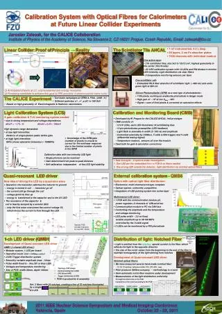
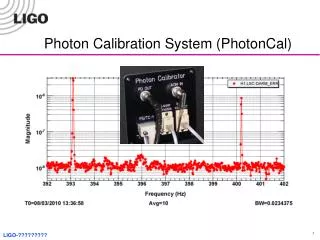
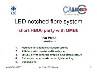
TCMT. AHCAL. 120 cm. 90 cm. ECAL. beam. The CALICE Experiment. 1-ch LED driver (QMB1). Distribution of light: Notched Fiber. Calibration System with Optical Fibres for Calorimeters at Future Linear Collider Experiments. Jaroslav Zalesak, for the CALICE Collaboration

E N D
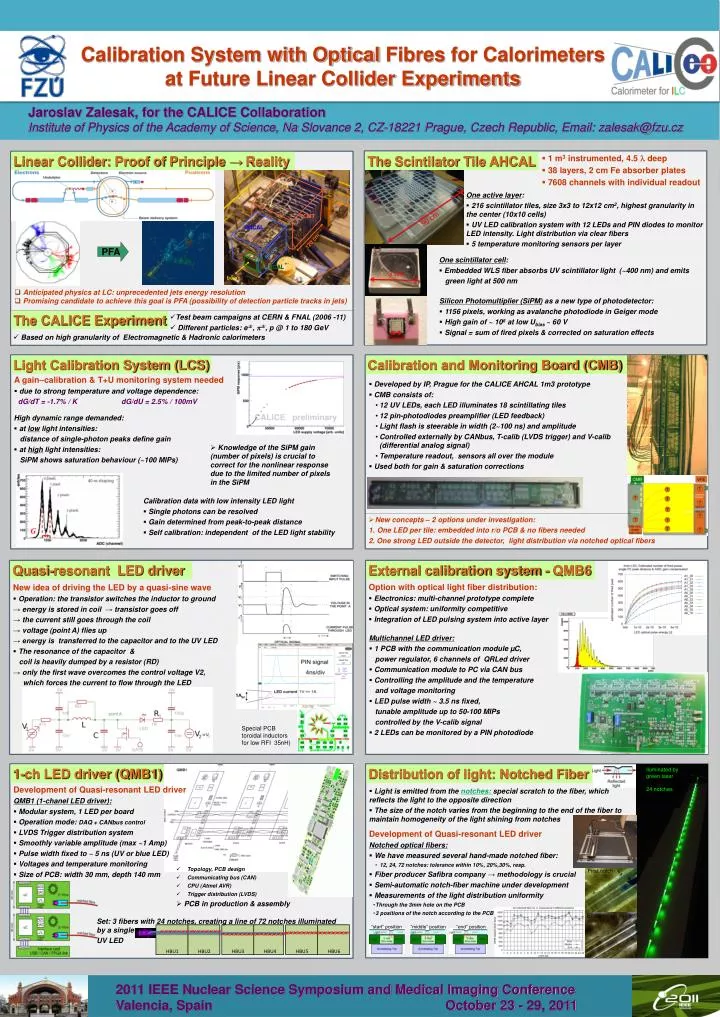
TCMT AHCAL 120 cm 90 cm ECAL beam The CALICE Experiment 1-ch LED driver (QMB1) Distribution of light: Notched Fiber Calibration System with Optical Fibres for Calorimeters at Future Linear Collider Experiments Jaroslav Zalesak, for the CALICE Collaboration Institute of Physics of the Academy of Science, Na Slovance 2, CZ-18221 Prague, Czech Republic, Email: zalesak@fzu.cz “start” position “middle” position “end” position HBU1 HBU2 HBU3 HBU4 HBU5 HBU6 Linear Collider: Proof of Principle →Reality The Scintilator Tile AHCAL • 1 m3 instrumented, 4.5 l deep • 38 layers, 2 cm Fe absorber plates • 7608 channels with individual readout One active layer: • 216 scintillator tiles, size 3x3 to 12x12 cm2, highest granularity in the center (10x10 cells) • UV LED calibration system with 12 LEDs and PIN diodes to monitor LED intensity. Light distribution via clear fibers • 5 temperature monitoring sensors per layer PFA One scintillator cell: • Embedded WLS fiber absorbs UV scintillator light (~400 nm) and emits • green light at 500 nm 90 cm • Anticipated physics at LC: unprecedented jets energy resolution • Promising candidate to achieve this goal is PFA (possibility of detection particle tracks in jets) Silicon Photomultiplier (SiPM) as a new type of photodetector: • 1156 pixels, working as avalanche photodiode in Geiger mode • High gain of ~ 106 at low Ubias~ 60 V • Signal = sum of fired pixels & corrected on saturation effects • Test beam campaigns at CERN & FNAL (2006 -11) • Different particles: e±, p±, p @ 1 to 180 GeV • Based on high granularity of Electromagnetic & Hadronic calorimeters 3 cm Light Calibration System (LCS) Calibration and Monitoring Board (CMB) • A gain–calibration & T+U monitoring system needed • due to strong temperature and voltage dependence: • dG/dT = -1.7% / K dG/dU = 2.5% / 100mV • Developed by IP, Prague for the CALICE AHCAL 1m3 prototype • CMB consists of: • 12 UV LEDs, each LED illuminates 18 scintillating tiles • 12 pin-photodiodes preamplifier (LED feedback) • Light flash is steerable in width (2~100 ns) and amplitude • Controlled externally by CANbus, T-calib (LVDS trigger) and V-calib (differential analog signal) • Temperature readout, sensors all over the module • Used both for gain & saturation corrections 1 mm • High dynamic range demanded: • at low light intensities: distance of single-photon peaks define gain • at high light intensities: SiPM shows saturation behaviour (~100 MIPs) • Knowledge of the SiPM gain (number of pixels) is crucial to correct for the nonlinear response due to the limited number of pixels in the SiPM Calibration data with low intensity LED light • Single photons can be resolved • Gain determined from peak-to-peak distance • Self calibration: independent of the LED light stability • New concepts – 2 options under investigation: • One LED per tile: embedded into r/o PCB & no fibers needed 2. One strong LED outside the detector, light distribution via notched optical fibers External calibration system - QMB6 Quasi-resonant LED driver • Option with optical light fiber distribution: • Electronics: multi-channel prototype complete • Optical system: uniformity competitive • Integration of LED pulsing system into active layer • New idea of driving the LED by a quasi-sine wave • Operation: the transistor switches the inductor to ground • → energy is stored in coil → transistor goes off • → the current still goes through the coil • → voltage (point A) flies up • → energy is transferred to the capacitor and to the UV LED • The resonance of the capacitor & • coil is heavily dumped by a resistor (RD) • → only the first wave overcomes the control voltage V2, • which forces the current to flow through the LED • Multichannel LED driver: • 1 PCB with the communication module µC, power regulator, 6 channels of QRLed driver • Communication module to PC via CAN bus • Controlling the amplitude and the temperature • and voltage monitoring • LED pulse width ~ 3.5 ns fixed, tunable amplitude up to 50-100 MIPs controlled by the V-calib signal • 2 LEDs can be monitored by a PIN photodiode Special PCB toroidal inductors for low RFI 35nH) Iluminated by green laser 24 notches • Development of Quasi-resonant LED driver • QMB1 (1-chanel LED driver): • Modular system, 1 LED per board • Operation mode: DAQ + CANbus control • LVDS Trigger distribution system • Smoothly variable amplitude (max ~1 Amp) • Pulse width fixed to ~ 5 ns (UV or blue LED) • Voltages and temperature monitoring • Size of PCB: width 30 mm, depth 140 mm • Light is emitted from the notches: special scratch to the fiber, which reflects the light to the opposite direction • The size of the notch varies from the beginning to the end of the fiber to maintain homogeneity of the light shining from notches • Development of Quasi-resonant LED driver • Notched optical fibers: • We have measured several hand-made notched fiber: • 12, 24, 72 notches: tolerance within 10%, 20%,30%, resp. • Fiber producer Safibra company → methodology is crucial • Semi-automatic notch-fiber machine under development • Measurements of the light distribution uniformity • Through the 3mm hole on the PCB • 3 positions of the notch according to the PCB • Topology, PCB design • Communicating bus (CAN) • CPU (Atmel AVR) • Trigger distribution (LVDS) • PCB in production & assembly First notch End position notch • Set: 3 fibers with 24 notches, creating a line of 72 notches illuminated by a single • UV LED 2011 IEEE Nuclear Science Symposium and Medical Imaging Conference Valencia, Spain October 23 - 29, 2011