Download
1 / 21
210 likes | 318 Vues
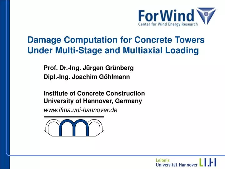
Damage Computation for Concrete Towers Under Multi-Stage and Multiaxial Loading. Prof. Dr.-Ing. Jürgen Grünberg Dipl.-Ing. Joachim Göhlmann Institute of Concrete Construction University of Hannover, Germany www.ifma.uni-hannover.de. Table of Contents. Introduction Fatigue Verification

E N D
Damage Computation for Concrete Towers Under Multi-Stage and Multiaxial Loading Prof. Dr.-Ing. Jürgen Grünberg Dipl.-Ing. Joachim Göhlmann Institute of Concrete ConstructionUniversity of Hannover, Germany www.ifma.uni-hannover.de
Table of Contents • Introduction • Fatigue Verification • Energetical Damage Model for Multi - Stage Fatigue Loading • Multiaxial Fatigue • Summary and Further Work
1. Introduction Nearshore Foundation Emden Hybrid Tower Bremerhaven
Fatigue Design for … Reinforcement Junctions Concrete Tendons
1 Scd,min = 0,8 0,8 0,6 Scd,max 0,4 0,2 Scd,min = 0 0 0 7 14 21 28 logN 2. Fatigue Verification by DIBt - Richtlinie Linear Accumulation Lawby Palmgren and Miner: Design Stresses for compression loading: Scd,min = sd ∙ σc,min ∙ c / fcd,fatScd,max = sd ∙ σc,max ∙ c / fcd,fat Ni = Number of load cycles for current load spectrumNFi = Corresponding total number of cycles to failure log N S – N curves by Model Code 90
The mechanical work, which have to be applied to obtain a certain damage state during the fatigue process, is equal to the mechanical work under monotonic loading to obtain the same damage state. ! Wda(D) = Wfat (D, fat, N) c fat Fatigue Process Monotonic Loading Elastic-Plastic Material Model for Monotonic Loading: c = (1 - Dfat) ∙ Ec ∙ (c - cpl) 3. Energetical Fatigue Damage Model for Constant Amplitude Loading by [Pfanner 2002] Assumption:
Scd,max,3 Scd,max,2 Scd,max,1 Extended Approach for Multi-Stage Fatigue Loading Life Cycle: Lfat = Dfat ( σifat, Ni) / Dfat ( σFfat, NF)≤ 1 Number of load cycles until failure: NF = Ni + Nr Scd,min,i
Three-Stage Fatigue Process in Ascending Order Fatigue Damage Dfat Ni
Computed Stress and Damage Distribution Dfat = 0,221 Dfat = 0,12 Dfat = 0,08 Dfat (N = 109) (N = 109) (N = 1) 1st Principal Stress Fatigue Damage
4. Multiaxial Fatigue Loading Joint of Concrete Offshore Framework Junction of Hybrid Tower Floatable Gravity Foundation
Fracture Envelope for Monotonic Loading TensionMeridian fcc / fc / fc ft ftt fc fcc fc fc = unaxial compression strengthfcc = biaxial compression strengthft = uniaxial tension strengthftt = biaxial tension strenth Compression Meridian Main Meridian Section
Fatigue Damage Parameters for Main Meridians cfat; tfat
Main Meridians under Multiaxial Fatigue Loading TensionMeridian fcc ft ftt fc Compression Meridian
Failure Curves for Biaxial Fatigue Loading Log N = 7 Log N = 6 Log N = 3 22,max / fc N = 1 min = 0 fc fcc 11,max / fc = 1,0 = - 0,15
Modification of Uniaxial Fatigue Strength Scd,min = sd ∙ cc ∙ σc,min ∙ c / fcd,fat Scd,max = sd ∙ cc ∙ σc,max ∙ c / fcd,fat
1 Scd,min = 0,8 0,8 0,6 Scd,max 0,4 0,2 Scd,min = 0 0 0 7 14 21 28 logN Modified Fatigue Verification Design Stresses: Life Cycle: Scd,min = sd ∙ cc ∙ σc,min ∙ c / fcd,fatScd,max = sd ∙ cc ∙σc,max ∙ c / fcd,fat Lfat = Dfat ( σifat, Ni) / Dfat ( σFfat, NF)≤ 1 S – N curves by Model Code 90
5. Summary and Further Work • The linear cumulative damage law by Palmgren und Miner could lead to unsafe or uneconomical concrete constructions for Wind Turbines. • A new fatigue damage approach, based on a fracture energy regard, calculates realistically damage evolution in concrete subjected to multi-stage fatigue loading. • The influences of multiaxial loading to the fatigue verification could be considered by modificated uniaxial Wöhler-Curves. • Further Work:Experimental testings are necessary for validating the multiaxial fatigue approach.
New workplace from June 2007: ENGINEERING EXPO PLAZA 10 Hannover, Germany www.grbv.de info@grbv.de