Download
1 / 44
1.89k likes | 3.42k Vues
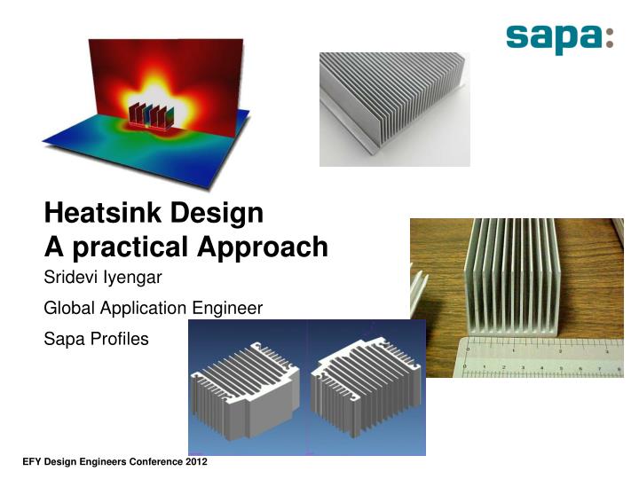
Heatsink Design A practical Approach. Sridevi Iyengar Global Application Engineer Sapa Profiles. Agenda. Introduction Heat sinks and Heat Transfer mechanisms Why use a heatsink Some facts you (N)ever wanted to know about heatsink Thermal Interface materials Liquid coolers

E N D
Heatsink Design A practical Approach Sridevi Iyengar Global Application Engineer Sapa Profiles
Agenda • Introduction • Heat sinks and Heat Transfer mechanisms • Why use a heatsink • Some facts you (N)ever wanted to know about heatsink • Thermal Interface materials • Liquid coolers • Friction Stir Welding
About Me – Sridevi ( Sri ) • Joined Sapa in 2010 • Have 10+ years of experience in electronics cooling and thermal design. Worked mostly at telecom/networking companies or consulted for projects in these areas. • Thermal Analysis, thermal testing – some of my key strengths, area of expertise • Icepak, Flotherm, and currently Flow Simulation are the tools I have used extensively for thermal simulations • Education • B.S – Chemical Engineering – NITK Suratkal ( Karnataka Regional Engg College) • M.S - Computational fluid Dynamics – University of California San diego • Passionate about South Indian Classical Music. I learn, teach and perform regularly
What is a heatsink • Heatsinks are devices that enhance heat dissipation from a component to a cooler ambient – usually air, but sometimes to other fluids as well. • The primary purpose of a heatsink is to maintain the temperature of the device being cooled within acceptable limits as specified by the component manufacturer. • Keeping the component temperature under the specified limits ensures proper operation of the device, and improves reliability and life of component.
Factors to be considered while designing heatsinks • Power that needs to be dissipated • Maximum allowable component temperature • Available space/volume for heatsink • Power density • Air Flow parameters • Pressure Drop • Bypass effects • Manufacturability • Costs
Heat sinks for air cooling Aluminium alloys are the dominating materials for air-cooled heat sinks
Thermal conductivity of Al-alloys Copper (pure): 395 W/mK
Principles of heat transfer • Heat transfer is “the science which seeks to predict the energy transfer which may take place between material bodies as a result of temperature difference • The three modes: • Conduction: Energy transfer within solids • Convection: Transfer from a surface to a moving fluid • Radiation: transfer by electromagnetic radiation
Convection Cooling • Convection cooling achieved by two ways • Forced Convection • Air is forced over the components with a fan or blower • The velocity of air depends on the fan and the local conditions • Natural Convection or free • The buoyancy effect forces hot air to flow to the top and cold air to come to the bottom. • Typical velocity – 0.2 m/sec
Technical terms • Q = Total power that is dissipated by the device (s) being cooled – (W) • Tj= Junction temperature of the device • Tc= Case temperature of the device • Ts = Heatsink temperature - Maximum temperature of the heatsink at a location closest to the device • Ta = Ambient temperature
The basic equation The governing equation which correlates the total power, temperature difference and the thermal resistance can be expressed as The thermal resistance is analogous to the electrical resistance used in Ohm’s law.
Thermal Resistance = Rj-c is the Junction to case thermal resistance. Usually a parameter that is published by the component manufacturer Rc-s is the thermal resistance across the thermal interface material between the heatsink and the component. Rs-a is the thermal resistance of the heatsink. Junction to Ambient is the sum of the resistances =
Heatsink Selection Tj, Rjc and Q will be provided by the component manufacturer. Rcs – Thermal resistance of the interface material Ta – Ambient temperature Ta and Rcs are parameters that we can control to a certain extent Rsa is the number that will help us identify a heatsink that will meet our criteria.
Heatsink Design parameters • A heatsink can be optimised for performance by varying the different dimensions shown. • Of course, the optimised design should consider manufacturability.
Low pressure-drop High pressure-drop Optimal operating region Characteristic curve of the fan Air-cooled heat sinks forced convection - fan curve Fan law: Air flow ∝ n (rpm) Pressure drop ∝ n2 Noise ∝ n3
T_fin => T_air Low efficiency Heat flow Fin efficiencyApparent cooling area vs. effective cooling area q = h·A ·(Ths-Tair)
Bypass Effects in Forced Convection When there is a significant gap between the heatsink and the top surface of the enclosure air will bypass the heatsink. This reduces the performance of the heatsink. Bypass effect is more pronounced in heatsinks with closely packed fins. HHeatsink Fin HHeatsink Base Here the air is forced to go through the heatsink and in this case the performance of the heatsink is optimised.
α Heat source Conical fins vs. rectangular fins Conical fins seems have some advantages when only heat flow is considered Die casting always need a relief angle !
Air flow in a conical channel When both air flow and heat flow are considered, rectangular fins are better
Heat sink orientationnatural convection • The buoyancy effects of air forces hot air to move up and cold air to come down. • Orient the heatsink keeping in mind the direction of gravity • Fin thickness and fin pitch are important factors to consider while optimising the heatsink. gravity
Comments on heat sinks used for natural convection • Optimise the fin spacing according to temperature and height. • Proper orientation of the heatsink with respect to gravity is important. • Radiation heat transfer must be considered. • Proper surface treatment is often needed as this increases the emissivity.
Heatsink OrientationForced convection • Fluid is forced to flow over the surface by external help (Fan) • Orient the heatsink in the direction of the Airflow. • Sometimes when the flow is erratic, can use pin fin heatsinks. • In general, extruded plane fin heatsinks work better and have lesser pressure drop across the Heatsink.
Comments on Heatsinks used for forced convection • Design must take the fan curve (and by-pass flow) into account when appropriate. • Check the fin efficiency when the fin is fairly tall. • Avoid using conical fins. • Optimise the base thickness, fin thickness and fin spacing based on the expected air velocity through the channels. • Always remember that when you have more than one heatsink in the system, the airflow to the downstream heatsink will be affected by the upstream heatsinks and components.
Heat sink Heat source Conduction, contact surface Actual contact area < 2% of apparent contact area • Perfect contact can never be ensured between the heatsink and the package. • This could lead to potential problems since trapped air acts as an insulator. • The performance of the heatsink can be much lower than estimated leading to high component temperatures. • To combat this problem, it is necessary to use a thermal interface material.
Thermal interface materials –Different types • Double sided PSA • Pressure sensitive adhesive is used to adhere the heatsink to the heat source • Easy to assemble with protective liner tabs • The component package type will determine the kind of tape to use – acrylic based or silicone based • The thermal conductivity of these tapes are moderate and depends on their thermal performance depends on the contact area that can be achieved between the bonding surfaces • Typically 0.005 -0.10 “ thick • Not recommended when the heatsink fins are oriented vertically – i.e along the direction of gravity • Single sided PSA • Provides adhesion only to the heatsink. • Mechanical fastening of the heatsink to the component is needed. • Typically 0.05 – 0.01” thick
Thermal interface materials –Different types • Phase Change Material • Available as peel and stick pads at room temperature • When heated the material reflows to fill all the interface voids • Very good performance – high thermal conductivity • Conforms to minimize thermal path thickness • Mechanical fastening of heatsink is required • Could be messy during re-work • Gap Filler • Soft, thermally conductive silicone elastomers. Used in places where a large and variant gap exists between the components and heatsink • Typically used in places where a common heatsink is used for multiple components • Mechanical fastening of heatsink required • 0.5mm – 5 mm thickness
Thermal interface materials –Different types • Epoxy • Room temperature vulcanizing materials which function both as thermal pathway and mechanical attachment • Not favored by assemblers due to the possible prep work and inability to rework • Grease • Excellent thermal conductivity and void filling capability • Mechanical attachment of heatsink to component required • Can be messy and not favored by assemblers • Can be as thin as 0.01”
What Next • At some point one reaches the limit of Air cooling. • You may enhance the performance of the heatsinks with different techniques like, serrated fins, bonded fins, Skived fins. • Heatpipe heatsinks, Vapor chamber and Liquid cooled heatsinks are the next generation of thermal management products when Air cooled heatsinks just will not do the job for you.
Heat pipe Heat pipe Vapour flow wick Condense returning (by capillary) Heat in Heat out
Conventional definition in automotive analogy Circulating fluid driven by pump Heat absorbed at source by “cold plate! Or “water block” Heat rejected to ambient by “heat exchanger” or “radiator” Multiple heat sources possible in series or parallel May also include two phase flow, evaporating at heat source, e.g. Heat pipe Thermsyphon What is “liquid cooling”?
Heat source Heat source 15 Liquid cooling: Channel design is important. 30 199
Liquid cooling: temperature & flow “Star channel” Sapa’s channel
Disadvantages of liquid cooling:System becomes more complex • Add significant complexity: more parts and more units being involved • Pump reliability • Low heat flux parts still need cooling with heatsinks/Fans • Investment required for testing and verifying system performance • Still need to remove heat from liquid system to ambient air (or other liquid) • In general, liquid cooling units will require more real estate.
Some comments on liquid cooling • Channel design is important. • Contact thermal resistance between component and heat sink may becomes significant. • The choices of liquid (coolant) depends on single phase or two phase.
Friction stir welding A rotating tool is plunged into the joint line and moved along the joint. Neither flux nor filler material are used. Friction Stir welding method of joining is based on the fact that the metal is subjected to heavy plastic deformation at high temperatures, but lower than the melting point. When the rotating tool is plunged into the metal, friction heat is generated. The tool produces severe plastic deformation under high pressure, during which the weld interfaces are stirred together and a homogenous structure is formed. Process results in completely pore-free,tight joints with a high strength Minimum heat influence on the material Good mechanical properties
Final Thoughts • Global market for Electronic Thermal management is forecasted to reach $8.6 billion by 2015. • Miniaturization of products along with increase in features is leading to higher power dissipations and more importantly power density • Upfront, well thought out thermal design will eliminate thermal related problems at later stages. At this time there might be no recourse or if there is one, it might be an expensive one. • Working closely with your thermal solutions provider will ensure you have a solid thermal solution for your electronic product.
Thank You • Feel free to contact me if you think I can be of any help. • Sridevi.iyengar@sapagroup.com • 91 – 99000 45726 • Some websites that I visit for information on thermal design • www.coolingzone.com • www.electronics-cooling.com