Download
1 / 28
280 likes | 284 Vues
Get the latest updates on the commissioning progress of the Booster and Storage Ring RF Systems at ALBA synchrotron light source in Barcelona, Spain.

E N D
The RF Group:Paco Sanchez Angela Salom Bea Bravo (since Oct. 2009) Support Engineering Division Support Computing Division Support Operators Group
ALBA overview and status • Booster RF System • Storage Ring RF System • Next
Synchrotron Light Source in Cerdanyola (Barcelona, Spain) December 2009
ALBA Accelerators LINAC 100 Mev BOOSTER 100 MeV – 3 GeV STORAGE RING 3 GeV
Booster commissioning started: • - 2 weeks in January • - 2 weeks in July • - Afternoons since Monday 27.09 • SR installation completed. Some testing of subsystems pending. • SR commissioning starts November 2010 without IDs. • SR commissioning with IDs by March 2011 • 1st beam for beamlines commissioning April 2011
BOOSTER COMMISSIONING “Stored Beam 100 MeV”: RF ON 5 seconds, 5 injections
BOOSTER COMMISSIONING 1st Synchrotron Light in Spain
BOOSTER COMMISSIONING 2.7 GeV with 0.7 mA 90 % Energy and 70% current of nominal values January 2010
Booster Transmitter Spring 2009: • DC Commissioning (with Thomson) Oct - Nov 2009: • RF Power Commissioning (with Thomson) -RF shutter closed and full RF power on load- • SAT passed on November 5th, 2009
Booster Cavity November 2009: • Cavity installed and aligned • Vacuum OK • Cabling and Sensors installed • Water cooling connected • Air cooling (RF window and WATRAX) • EPS and interlock OK
Booster LLRF: Conditioning and Calibration • Nov – Dec 2009: • Full RF Plant ready • Tunnel closed (Operation in parallel with the Bo PS testing) • 60 kW in the cavity (35 kW used during Booster commissioning) • Calibration done
Stored Beam: RF ON LLRF: Automatic Start up • Feb 2010: • After the experience during the Booster commissioning • To easy the recovery after a trip • To avoid operator errors • Automatic Start up:
Automatic Start up: - After a trip LLRF set all parameters to minimum: - Low RF drive - Disable tuning - Open loops (I&Q) - Operator reset the interlock and switch on the transmitter - LLRF detect the presence of RF power at cavity input - LLRF tune the cavity before allowing high power - LLRF close the loops and check loops stability - Smooth power increase - Message RF ready for beam RF Power Tuning pulses Plungers direction
RF Voltage 3600 kV Digital LLRF TRANSMITTER Tube type IOT Number 6 x 2 IOTs Power 2 x 80 kW Combination CaCo Layout 6 cavities
SR Transmitters March - September 2010: • RF Commissioning (with Thomson) • 12 SR transmitters has passed the SAT • Details by Paco Sanchez
SR Dampy Cavities Conditioning at RF lab April 2009 to January 2010
SR Dampy Cavities • All 6 performing well • Installed and bake-out in situ • Alignment, cabling and cooling ready
Waveguide system: Circulator problems Ferrite Inc. (USA) • Control by minimising the VSWR: • Measure forward and reflected power • Compute VSWR • Act on the PS of the circulator Problems during cavity conditioning: Pulsed conditioning: No responding due to slow control CW conditioning: During autotune it changes slightly the IOT load, i.e. IOT power, so sudden increase of power to the cavity and (ussualy) a vacuum trip.
Waveguide system: Circulator problems Bias current drift Solution: Condition the cavities with the circulator on Manual Mode (no very convenient, but ok) In addition we have to send a circulator back to Ferrite since it was wrongly adjusted to cope with 160 kW of power.
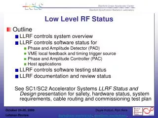
Digital LLRF System All modules installed: • Analogue Front ends • Amplitude and Phase Control Loop • Tuning loop • Timing system • RF detectors • Arc detector • Fast Interlock Modules (FIM)
Conditioning and Calibration • June – September 2010: • All RF Plants ready • Cavities: • Four cavities conditioned up to 70 kW • One cavity under conditioning this week • Last cavity under cooling reparation (flowmeters) • Calibration on going
NEXT: • ALBA commissioning: • Linac + Booster + SR + Beamlines • CaCo improvement: • See Bea presentation • Linac RF pulse digitalisation: • …
Linac RF pulse digitalisation RF Linac Pulses Characteristics • RF Frequency: 500MHz & 3GHz • Pulse width: 4μs • Repetition rate: 1Hz – 3Hz Available RF Signals • Fw PB1, FwPB2 & FwB, FwK1 & FwK2, FwAS1 & FwAS2
Front End • Downconversion of 3GHz signals to 500MHz (IF) • LO: 3.5GHz Digital Board • 8 ADCs and Virtex-4 • IF signals undersampled at 80MHz • Amp & Ph information to CS Control System (CS) • At present: Manual Phase adjustment of RF signals • Next Step: Automatic phase adjustment Pulse 4us Amplitude Resolution First Tests (4us pulse) • Amp Error: 0.2mVpp • Phase error : 0.6ºpp Phase Resolution