Download
1 / 37
370 likes | 532 Vues
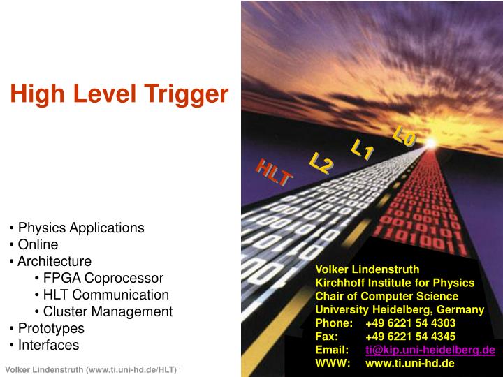
L0. L1. L2. HLT. High Level Trigger. Physics Applications Online Architecture FPGA Coprocessor HLT Communication Cluster Management Prototypes Interfaces. Volker Lindenstruth Kirchhoff Institute for Physics Chair of Computer Science University Heidelberg, Germany

E N D
L0 L1 L2 HLT High Level Trigger • Physics Applications • Online • Architecture • FPGA Coprocessor • HLT Communication • Cluster Management • Prototypes • Interfaces Volker Lindenstruth Kirchhoff Institute for PhysicsChair of Computer Science University Heidelberg, Germany Phone: +49 6221 54 4303 Fax: +49 6221 54 4345 Email: ti@kip.uni-heidelberg.de WWW: www.ti.uni-hd.de
HLT functionality • Trigger • Accept/reject events • verify dielectron candidates • sharpen dimuon transverse momentum cut • identify jets • ... • Select • Select regions of interest within an event • remove pile-up in p-p • filter out low momentum tracks • ... • Compress • Reduce the amount of data required to encode the event as far as possible without loosing physics information
HLT responsibilities • HLT reponsibilities • Process unmodified RAW events from detectors in order to enhance selectivity and reduce data volume on tape • Perform on-line event reconstruction • Select events or sub-events • Implement detector specific loss-less and possibly binary lossy data compression on selected data • Physics simulations • HLT Algorithms
Physics Applications • Quarkonium spectroscopy • Dielectrons • Dimuons • Open Charm • Jets • Pileup removal in pp
Quarkonium - dielectrons (1) • TRD trigger rate • 300-700 Hz at dN/dy = 8000 • 100-250 Hz by selecting two invariant mass windows around the J/ and the family • HLT task • Reject fake triggers and reduce trigger rate by factor of 10 • Trigger strategy • Re-analysis of TRD tracking and PID • Precise tracking of dielectron candidates in TPC • Sharpening the electron pt-cut and rejecting low-pt triggers • Combined track fit TRD-TPC-ITS • Rejecting secondary electrons by impact parameter cut • Additional PID by dE/dx • Rejection of background tracks (mainly misidentified pions) by combined (TRD+TPC) PID
Quarkonium - dielectrons (2) • Particle identification by dE/dx in the the TPC • dE/dx for 4 GeV/c pions (red) and electrons (blue) • Pion rejection power; ideal case (red) and dN/dy=4000 event (black) • Rejection factors • Low pt, seconday electrons (50% of background) • Precise tracking: factor 2 • Impact parameter cut: factor 2 • Misidentified tracks (50% of background) • Improved PID: factor >10 • HLT output trigger rate • Few Hz
Quarkonium - dimuons • Utilizing tracking chamber information • Improving momentum resolution • Sharpening of pt-cut • Preserves signal • Rejects background • Rejection factors • Low pt-cut: 5 • High pt-cut: 100 Significant reduction in event rate F. Manso et al., ALICE-INT-2002-04
Jets • TPC jet cone finder • Trigger efficiency: 50-70% (>100 GeV) • Fake triggers:2–4 Hz
L0 ~2 kHz L1 A L1 A TRD Global L0 Trigger Trigger Readout Readout Readout Readout Readout Readout Readout Readout Readout Readout Other Trigger L1 TRD TRD TPC TPC Di Di Muon Muon ITS ITS Detectors ; L0 Pretrigger L2 L2 accept D-RORC DAQ-LDC 18 DDL, 8 MB/event 216 DDL, 83 MB/ event 10 DDL, 500 kB / event Zero Zero suppressed suppressed Zero Zero suppressed suppressed Zero Zero suppressed suppressed Zero Zero suppressed suppressed TRD raw data TRD RAW Data TPC TPC raw data RAW Data DiMuon RAW Data ITS RAW ITS raw data Data Dimuon raw data +TRD +TRD Tracklets Tracklets Sector Sector parallel parallel +ITS Vertex +ITS vertex Cluster Cluster Cluster Cluster Cluster Cluster Finder Finder Finder Finder Finder Finder TRD Primary Vertex Seeds , locator RoI HLT On On - - line line On On - - line line On On - - line line Tracker Tracker Tracker Tracker Tracker Tracker TRD HLT General HLT DiMuon HLT Verify e + e - hypothesis trigger decision , Readout RoI definition Refine L0/L1 trg . On - line Data Reduction RoI readout , vector quantization , tracklet readout Time, causality Fine grain RoI r eject e + e - tracks Track segments enable event RoIs Space points Binary loss less Data compression (RLE, Huffman, LZW, etc.) 0.5-2 MB/event 4-40 MB/event 80 MB/event DAQ-LDC
Tracking efficiency before and after comp. Relative pt-resolution before and after comp. Tracking efficiency Relative pt resolution [%] Compression factor: 7-10 dNch/d=1000 Data Compression Standard loss(less) algorithms; entropy encoders, vector quantization ... - achieve compression factor ~ 2 (J. Berger et. al., Nucl. Instr. Meth. A489 (2002) 406) Data model adapted to TPC tracking Store (small) deviations from a model: Cluster model depends on track parameters
HLT FPGA Coprocessor • RORC Baseline Architecture • RORC Design • Cluster-Finder • Hough Transform
200 MB/s max. per design ≈ 90 MB/s typical iCache iCache Data pointer Push readout Pointers CPU CPU List dCache dCache small FPGA Detector Derandom . Data Link PCI 66/64 Evt . Buffer iCache iCache PCI Hostbridge CPU CPU dCache dCache Network Interface Host memory PCI HLT FEP Architecture
FPGA Co-Processor • HLT-RORC V1.0 – 20 devices produced in 2002 • FPGA: APEX 20K400 • Next prototype: Altera Stratix FPGA • Large internal memory • DSP cores
Comparison CF - FPGA vs. Online Circle: Cluster Finder HLT on-line Dot: FPGA
HLT CommunicationFramework • Publish/Subscriber Frame-Work
Shared Memory New Event Event Input Data Subscriber Analysis Code Event Output Data Publisher New Event Analysis Components Analysis processes made up of three parts: Subscriber as data input for new event data. Processing code that works on the data in shared memory and possibly writes some new output data into shared memory. Publisher to make the resulting output data available. Read data Write data
New Event Publisher New Event Subscriber Publisher Publisher Subs Subs Merging Code Publisher Event Chain Building Blocks (Sub)Event Scatterer (Sub) Event Gatherer New Event New Event Subscriber Load balancing Fan-out Subscriber Publisher Subscriber (Sub)Event Merger Bridging between Nodes Event M Block 0 Event M Block 1 • SubscriberBridgeHead • Subscribes to upstream • Gets input data from publisher • Sends data over network • PublisherBridgeHead • Publishes to downstream • Reads data from network Event M Block 0, 1 …
HLT Simulations HL0 HL1 HL2
HLT ClusterManagement • Software Architecture • Hardware Architecture
Fault tolerance design Monitoringglobal server FT global server Local Monitoring Interface Actuator Decision Unit (DU) Actuator agent Actuator Actuator Sensor Rules Sensor Sensor Fault Tolerance daemon (FTd) Monitoring DataGRID – WP4
HLT Prototypes • HD HLT System • HLT Data Challenge • RORC / CIA • STAR L3
Heidelberg Cluster • 32 compute nodes • 2 server nodes • each node SCI 2D torus, 100BT, 1000BT Ethernet • Each node 2 CPUs, 500 MB, 40GB Network Card
Publisher / Subscriber Fault Tolerance Not a single event lost During error recovery
Interfaces • HLT input • HLT output • DCS • ECS • Off-line
HLT data input / output L2 R eject Detector L2 Accept D-RORC DAQ-LDC HLT input Detector Interface • detector raw data HLT HLT • HLT accept/reject • compressed data • raw readout list HLT output DATE Interface Causality, time DAQ-LDC
Continuing HLT Key activities • On-line event reconstruction • On-line pattern recognition • FPGA Coprocessor (assist to tracking) • On-line tracking • HLT Physics simulation • Trigger efficiency • Trigger selectivity • HLT Computer Architecture • HLT Decomposition, Assignment, Orchestration • HLT-RORC data input • Cluster management
Key Milestones • TPC Beam Time June 2004 • HLT with event display, on-line event reconstruction • HLT RORC • HLT RORC PRR September 2005 • HLT RORC production (some slack included) • HLT Commissioning September 2006 • Minimim 20% connectivity on site at CERN • HLT operational April 2007 • Full connectivity, reduced CPU power PRELIMINARY