Download
1 / 18
230 likes | 379 Vues
Modeling of the Current Distribution in Aluminum Anodization. Rohan Akolkar and Uziel Landau Department of Chemical Engineering, CWRU, Cleveland OH 44106. Yar-Ming Wang and Hong-Hsiang (Harry) Kuo General Motors R&D, Warren MI 48090.

E N D
Modeling of the Current Distribution in Aluminum Anodization Rohan Akolkar and Uziel Landau Department of Chemical Engineering, CWRU, Cleveland OH 44106. Yar-Ming Wang and Hong-Hsiang (Harry) Kuo General Motors R&D, Warren MI 48090. 205th Meeting of The Electrochemical Society, San Antonio, TX.
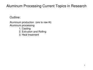
Outline • Anodic Oxide Films on Aluminum • Current distribution –Significance • Kinetics of oxide growth • Modeling of Current and Potential Distribution • Comparison with experiments • Effect of operating conditions (t, V, T) • Conclusions
Introduction • Aluminum Anodization • dc voltage = 12-20 V • Alloy 6111 • 15 wt. % H2SO4 • time = 15-35 min • oxide films ~ 5-25 μm 5-25 μm Oxide pores ~30 nm Al2O3 barrier Al metal
Important Issues in Al Anodization • Anodized parts with complex, non-accessible features experience large oxide thickness variations. • What are the current distribution characteristics inside non-accessible cavities ? • How are they affected by the operating conditions ? Objective • Analyze and model the current distribution in anodizing systems, and compare with experimental measurements.
Governing Equations Net Flux = Diffusion + Migration + Convection • Assume : • No concentration gradients • Steady state _ + zj Potential Distribution H+ v Boundary Conditions • Insulator (zero current) : • Electrode (Resistive Oxide) : Mott Cabrera Kinetics
Anodization kinetics Mott Cabrera Kinetics : i = A exp (B V) A, B: ionic transport parameters within the oxide film Increasing temperature VERY HIGH SURFACE RESISTANCE leads to VERY HIGH SURFACE OVER-POTENTIALS
Oxide Thickness Distribution _ Current Density : + Faraday’s law : current efficiency oxide porosity
Current and Potential Distribution Methods to compute current distribution Scaling Analysis e.g. Wagner number : Analytical Modeling e.g. analytical solution of current balance equations Numerical Modeling e.g. CELL DESIGN*, FEM, FDM to solve Laplace equation * CELL DESIGN, L-Chem Inc., Shaker Heights, Ohio 44120.
Experimental setup _ _ + Parallel plate anode assembly z y x 2.5 Anodes 43 Cathode Cathode 10 30 z z 0.8 x y 30 side shields
Numerical Modeling Geometry Potential Map Electrode Properties e.g. kinetics Cell Design’sBEM* Solver Current Distribution Electrolyte Properties e.g. conductivity Deposit Profile Oxide Properties e.g. porosity * Boundary Element Method
Simulation Results Significant potential drop ONLY in the interior of the parallel plates NON-UNIFORM oxide in the interior Potential Distribution Current Distribution
Measurement of Oxide Distribution for comparison with modeling results Anode 86 0 Uniform Oxide Cathode Non-Uniform Oxide 43 43 • Oxide thickness measured along the anode at ~5 cm intervals
Experimental vs. Modeling Non-uniform distribution in the interior Uniform oxide thickness on the exterior Anodic Oxide Thickness (microns) Distance Along the Electrode (cm)
Effect of Anodization Time 35 min Constant oxide resistance Anodic Oxide Thickness (microns) 15 min Distance Along the Electrode (cm)
Effect of Anodization Time –Distributed resistance Low growth rates for distributed resistance within entire oxide Constant oxide resistance Anodic Oxide Thickness (microns) 35 min 15 min Distance Along the Electrode (cm)
Effect of Anodization Voltage 18 V Uniform oxide Anodic Oxide Thickness (microns) Low oxide thickness inside the interior 14 V Distance Along the Electrode (cm)
Effect of Anodization Temperature 25 oC Uniform oxide Anodic Oxide Thickness (microns) Low oxide thickness inside the interior 15 oC Distance Along the Electrode (cm)
Main Conclusions • An electrochemical CAD software used to model the current distribution in anodizing. • Excellent agreement between modeling and experiments. • The oxide growth rates are independent of time indicating a porous oxide growth – the oxide resistance resides in a compact barrier film at its base. • Current distribution was highly non-uniform in high aspect ratio cavities due to dominance of ohmic limitations over surface resistance.