Download
1 / 42
420 likes | 426 Vues
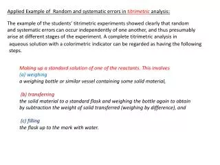
Learn about the errors that occur during sample and hold operations and discover solutions to mitigate these errors. Understand the impact of non-idealities and how to select the appropriate components for accurate signal transfer.

E N D
Sample and hold Also called track and hold, or acquire and hold Switch positions in track mode are shown Sampling happens at the instant when switches change positions Opposite positions are for hold mode
Sample and hold Errors • During tracking • There is a voltage drop across op amp + and ─ terminal • There is voltage drop across S1 and S2 as long as Vin is not constant, i.e., there is current • Both of the above cause Vcap ≠ Vin • Ron of S1 and S2 is also signal level dependent, making the above error non linear • This nonlinear error is also slope dependent, making it a dynamic error
Sample and hold Errors • During tracking • The two voltage drops also change when there are power supply variations, ground bounces, temperature variations, and 1/f noise. • These effects are common mode • Differential structures, such as the one shown, are much more robust with respect to such errors than single ended structures
Cap voltage in the presence of supply variations and ground bounces Single ended structure Differential structure Use differential signaling whenever possible Single ended input may need to be converted first
DAC output buffering Current to voltage Voltage to current Load driving capability Low pass filtering Band pass filtering BP application HD or IMD capturing
Differential current output DAC to single ended voltage conversion
HW • On the previous slide, assume ideal “conditions”, find the quiescent voltage at each node and quiescent current through each R or C, and label them. Find the small signal transfer function from iod to vo. Verify the approximate f_3dB. • Now include some non-idealities. I_out = I_oc + i_od, I_out_bar = I_oc - i_od, the op amp has finite gain Avd and Avc and has input parasitic capacitance C_p+ and C_p-. Still assume correct resistor values and infinite Ro for the current source. Op amp is also linear (gains constant). Find VoQ and small signal v_o.
Conditioning, level shifting, amplification, S.E. to Diff, DC vs ac coupling, etc.
Signal Swing and Common-Mode Range Termination for input source Approximately right only
HW Why RT? How to select RT? Then what’s the true gain? When is the approximation good? If v_in is within V_icm +- V_idsw, and if ADC has input range from V_min to V_max, how should V1, R1, R2 be selected?
Series Resistor, RS Tester Instrument and Connecting Cable DUT Output Termination Resistor, RT=Zo Transmission Line, Characteristic Impedance = Zo Series Resistor, RS Equivalent Load DUT Output Termination Resistor, RT=Zo
Single-Ended to Differential DC-Coupled Driver with Level Shifting
HW • Perform a DC analysis to verify the Q points. What’s the value of Vref? Find the small signal gain from input to Vin+ and small signal gain from input to Vin-. Why the value 53.6 is used? If the input source has internal resistance Rs = 50 Ohm, how does that affect the Q point and small signal? What would be the p-p value of the signal at the input of the ADC? Why is this actually beneficial?
HW • Why the value of the 200 Ohm resistor? What’s the value of Vcm. • Find the quiescent values at A, B, C, Vin+ and Vin-. • Find the signal range (Vmin to Vmax) at these points. • Find the small AC signal transfer function from the source to vid = vin+ –vin-.
Op Amp DC or AC Voltage Source (Vin) Iout = Vin / RS DUT RS V = RS * Iout = Vin Instrumentation Amplifier (High Impedance Inputs) Voltage to Current Conversions
Calibration/Checker Source R ATE Measurement Instrument Iout DUT Cal Relay Vout / IIn = -R Current to Voltage Conversions
Gain = -1 Calibration Instrument R AC Signal Source R DUT Vin VMID R R Vmid Reference Adder
RS DUT RM Load Resistance, RL Test Current, ITEST VTEST RM Device Zero (DZ) RG Device Ground Sense (DGS) Line Use Kelvin connection with 4, or five wires
HF Source 1 DC Meter IN+ HS LF LS IN- DIB HF Source 2 HS LF DUT LS DZ HF Source 3 HS Digitizer IN+ LF LS DGS Line IN-
Calibration Instrument DC Source VP R2 HF VDD PSRR Ripple Signal HS DUT LF R1 C LS Use Kelvin connection to add ripple for PSRR Ripple cannot be easily added to VDD directly LDO feedback rejects ripple being added
DIB Circuit Ground Input (High Impedance) DUT +5V Pin DUT AGND Pin DUT DGND Pin Layer 1 (Digital Signals) Layer 2 (DGND Plane) Layer 3 (Split Power Plane) Layer 4 (AGND Plane) Layer 5 (QGND Plane) Layer 6 (Analog Signals) AGND to DGND Connection (Single Point) Power Plane Split DZ Power and Ground Planes
Instrument Probe Tester Mainframe Test Head and DIB Bench Instrument Tester Instrument Ground Bench Instrument Safety Ground Tester Safety Ground Ground Loop Earth Ground Be careful with possible ground loops