Download
1 / 46
460 likes | 479 Vues
Learn about the principles of biped dynamic walking, ZMP definition, computing ZMP position, mechanical structure, stability, and legged robot locomotion techniques.

E N D
Robotics Course ZMP-BASED LOCOMOTION Lesson 22
DYNAMICAL WALKING • Biped dynamic walking allows the center of gravity to be outside the support region for limited amounts of time. • There is no absolute criterion that determines whether the dynamic walking is stable or not. • Indeed a walker can be designed to recover from different kinds of instabilities. • However, if the robot has active ankle joints and always keeps at least one foot flat on the ground then the Zero Momentum Point (ZMP) can be used as a stability criterion.
ZMP DEFINITION • The ZMP is the point where the robot's total moment at the ground is zero. • As long as the ZMP is inside the support region the walking is considered dynamically stable because is the only case where the foot can control the robot's posture. • It is clear that for robots that do not continuously keep at least one foot on the ground or that do not have active ankle joints (walking on stilts), the notion of support area does not exist, therefore the ZMP criterion cannot applied.
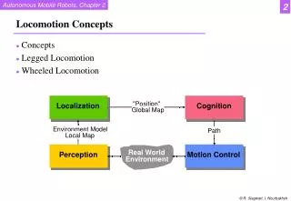
DYNAMIC WALKING SCHEMA • You can look at the figure
COMPUTING ZMP - I • The position of the ZMP is computed by finding the point (X, Y, Z ) where the total torque is zero. • Since we are only interested in the ground plane we assume that Z = 0. • To avoid confusion, torque and moment mean in this scenario the same thing. • The robot has n links; each link is subject to a • total forceFi applied at a point determined by the • vector Ri relative to the center of gravity of the link. • Ti determines the total motor torque applied to the link. • Rz is the ZMP vector and T is the robots total torque.
COMPUTING ZMP - II • An example of the forces applied to a link is represented in the figure
COMPUTING ZMP - III • The force, torque and position vectors have the following coordinates:
COMPUTING ZMP - IV • Then the total torque is computed as: • where x represents the cross product. The equation is then expanded as:
ZMP POSITION • Making Z=0 and solving these equations for X and Y we obtain the ZMP coordinates:
MECHANICAL STRUCTURE • The biped robot is configured of two legs, each having 4 degrees of freedom (DOF). • The trunk is used to stabilize the robot during the walking gait. • Three of these are rotational on the pitch axis at the hip, knee and ankle. • The fourth is also rotational an located at the hip on the yaw axis. • The trunk (an inverted pendulum) has 1 DOF. The trunk, used to stabilize the robot, • is moved to the angle calculated by the controller, the centre of mass (COM) position will change to a point were the robot's structure is stable.
STABILITY - I • In traditional legged robots, stability is maintained by having at least three contact points with the ground surface at all time. • With biped machines, only two points are in contact with the ground surface; for that reason algorithms to achieve balance must be implemented. • To solve the biped robot stability at walking, a simplified model of feet force sensors feedback can be used as a controlling input which tries to maintain stability at walking. • Even so the mechanical design goal is to ensure that the robot at walking will achieve dynamic balance.
STABILITY - II • Dynamic balance is partially provided by the control algorithm; however the mechanics design plays a very important role for the robot's ability to do the correct movements. • A way to reach it, is finding a correct mass distribution for the robot, thus the robot will be able to achieve the stability at walking. • These movements can therefore be made rapidly without generating large moments which would further destabilize the robot.
STABILITY - III • To achieve this, the COM should be placed in a location low enough to stabilize the robot inertially, but high enough so that it can be moved only small amounts to correct for undesired behavior. • The correct placing for the COM is the lower trunk, similar to humans. This provides for stability and allows the trunk to be moved, shifting the COM to achieve desired accelera-tions to counteract existing undesired accelerations.
LEGGED ROBOT LOCOMOTION • Three main approaches: • trajectory based methods, • heuristic control methods, and • cpg-and-reflex based methods
TRAJECTORY PLANNING • Question: how to generate good trajectories? • (Very) simplest options: • Provide a few desired positions (angles) over time (controller with step functions) • Provide smooth hand-tuned trajectories (e.g. with spline fitting) • These are open-loop solutions, i.e. no feedback to the trajectory planner
ZERO MOMENT POINT APPROACH • Method for proving that a trajectory is stable • Zero Moment Point (ZMP): point on the ground about at which the net moment of the inertial forces and the gravity forces has no component along the horizontal planes (a.k.a. center of pressure, CoP). • ZMP is different from the projection of the center of mass (CoM) on the ground • ZMP ~ projection on the ground of the point around which the robot is rotating
TRAJECTORY-BASED METHODS • Main idea: design walking kinematic trajectories, and use the dynamic equations to test and prove that locomotion is stable • Trajectories are designed by trial-and-error, or from human recordings • Most successful approach: Zero Moment Point (ZMP) method (Vukobratovic 1990)
ZMP APPROACH • Foot print polygon Locomotion is stable if the ZMP remain within the foot-print polygons
ZMP APPROACH • Most used method: • Human motion capture for getting trajectories, • Modify trajectories such that locomotion is stable according to the ZMP criterion • Add online stabilization to deal with perturbations • Example of online stabilization: • Use of hip actuators to manipulate the ZMP
ZMP APPROACH CONCLUSIONS • Pros: • Well-defined methodology for proving stability • Well-suited for expensive robots that should never fall
ZMP APPROACH CONCLUSIONS • Cons: • Requires additional online control to deal with perturbations • Transitions from online control back to desired trajectories can be tricky • Define good trajectories can be time-consuming • Requires a perfect knowledge of the robot’s dynamics and environment
PID CONTROLLER • Stands for Proportional Integrative Derivative Controller • A feedback controller extensively used in many devices, e.g. thermostat, robots, ...
CONTROLLER WITH STEP FUNCTION • Simply provide a new desired angle every so often: • Problems: • very saccadic motion, • depends strongly on PID gains
CONTROLLER WITH HAND-TUNED TRAJECTORIES • Provide a trajectory as a vector:
CONTROLLER WITH HAND-TUNED TRAJECTORIES • Hand-tuned trajectory: only give a few points and use of spline-fitting • Problems: • How to be sure that the locomotion is stable? • Need for mathematical tools to prove stability, such ZMP is.
OPEN-LOOP SINUS-BASED CONTROLLER • Desired angle for each DOF • Problem: finding, for each DOF i suitable
OPEN-LOOP SINUS-BASED CONTROLLER • Parameters can be found by hand, or using a genetic algorithm • For instance, genetic algorithm for optimizing the speed of walking
HEURISTIC CONTROL: VIRTUAL MODEL CONTROL • Most successful example: Virtual Model Control (G.Pratt) • Idea: create virtual elements to keep the robot upright and have it move forward • Then compute the necessary torques such that the robot motors replicate the effect of those virtual elements
HEURISTIC CONTROL: VIRTUAL MODEL CONTROL • For each virtual element producing a force F, the joint torque needed to produce that virtual force can be computed with: • J is the Jacobian relating the reference frame of the virtual element to the robot
VIRTUAL MODEL CONTROL • Only some motors should be activated at particular phases in the locomotor cycle • Finite state machine (set of if-then rules) for cycling through different actuation phases
VIRTUAL MODEL CONTROL: SUMMARY • Pros: • Intuitive way of designing a controller • Does not need an accurate model of the environment • Robust against perturbations • Cons: • Requires a perfect knowledge of the robot’s dynamics • Need to make sure that the virtual forces can actually be generated by the robot’s motors • Finite-state machine for cycling through the different phases is a somewhat rigid mechanism