Download
1 / 18
210 likes | 624 Vues
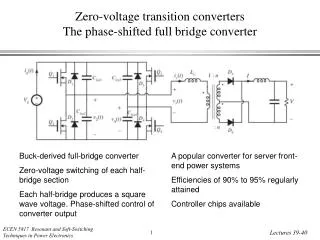
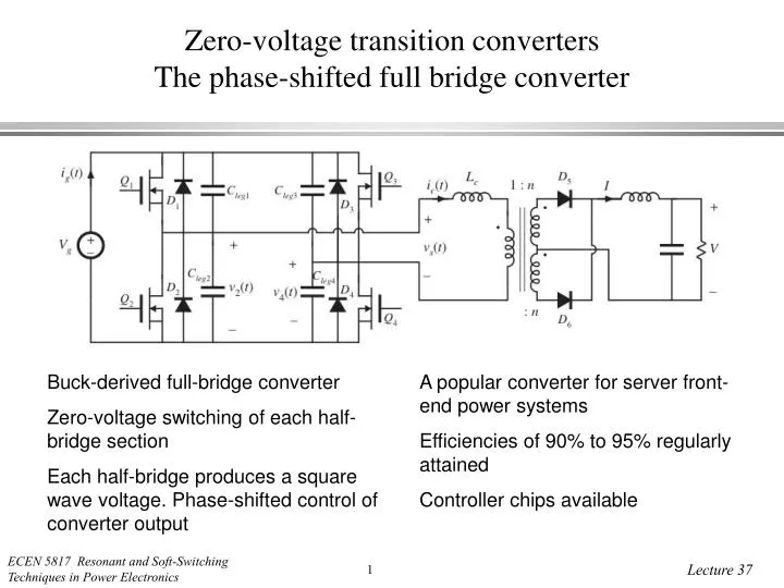
Zero-voltage transition converters The phase-shifted full bridge converter. Buck-derived full-bridge converter Zero-voltage switching of each half-bridge section Each half-bridge produces a square wave voltage. Phase-shifted control of converter output.

E N D
Zero-voltage transition convertersThe phase-shifted full bridge converter Buck-derived full-bridge converter Zero-voltage switching of each half-bridge section Each half-bridge produces a square wave voltage. Phase-shifted control of converter output A popular converter for server front-end power systems Efficiencies of 90% to 95% regularly attained Controller chips available
Phase-shifted control • Approximate waveforms and results • (as predicted by analysis of the parent hard-switched converter)
Result of analysisBasic configuration: full bridge ZVT • Phase shift assumes the role of duty cycle d in converter equations • Effective duty cycle is reduced by the resonant transition intervals • Reduction in effective duty cycle can be expressed as a function of the form FPZVT(J), where PZVT(J) is a negative number similar in magnitude to 1. F is generally pretty small, so that the resonant transitions do not require a substantial fraction of the switching period • Circuit looks symmetrical, but the control, and hence the operation, isn’t. One side of bridge loses ZVS before the other.
Subinterval 5 ZVS: output current charges Cleg without requiring J > 1
Subinterval 6 • Current ic circulates around primary-side elements, causing conduction loss • This current arises from stored energy in Lc • The current is needed to induce ZVS during next subinterval • To maxzimize efficiency, minimize the length of this subinterval by choosing the turns ratio n such that M = V/nVg is only slightly less than 1
Subintervals 7 to 11 • Subintervals 7 to 11 and 0 are symmetrical to subintervals 1 to 6 • Complete state plane trajectory: