Download
1 / 43
430 likes | 631 Vues
I/O Management and Disk Scheduling. G.Anuradha Ref: Stallings. Contents. I/O Devices Organization of the I/O Function Operating System Design Issues I/O Buffering Disk Scheduling RAID Disk Cache. I/O Devices. External devices can be categorized into

E N D
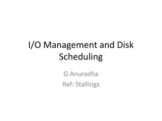
I/O Management and Disk Scheduling G.Anuradha Ref: Stallings
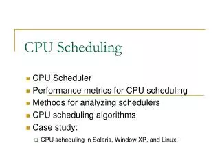
Contents • I/O Devices • Organization of the I/O Function • Operating System Design Issues • I/O Buffering • Disk Scheduling • RAID • Disk Cache
I/O Devices • External devices can be categorized into • Human readable:- Eg. Printers, visual display terminals, keyboards, mouse • Machine readable:- Eg: disk and tape drives, sensors, actuators • Communications:-Modems Differences exist among these classes
Differences • Data rates: data transfer rates range from 101 to 109 • Applications: how the device is used has an influence on the software and policies in the OS and supporting utilities • Complexity of control: depends on the device. Printer –simple control when compared to a disk • Unit of transfer: as bytes or characters • Data representation: different data encoding schemes • Error conditions: different from device to device
Organization of the I/O function • Programmed I/O : • Processor issues an I/O command on behalf of the process to an I/O module • Process then buzy waits for the operation to be completed • Interrupt-Driven I/O • Processor issues an I/O command on behalf of the process to an I/O module • Continues to execute instructions • Interrupted by I/O when the latter has completed its work • Direct Memory Access • Controls the exchange of data between main memory and an I/O module. • Processor sends a request for the transfer of a block of data to DMA • Interrupted only after the entire block has been transferred
Evolution of the I/o Function • The processor directly controls a peripheral device • A controller or I/O module is added and processor uses programmed I/O without interrupts • I/O module with interrupts • The I/O module is given direct control of memory via DMA. • I/O module is enhanced to I/O processor; CPU directs the I/O processor to execute an I/O program in main memory • I/O module has a local memory of its own. With this architecture, a large set of I/O devices can be controlled
Direct memory Access • When processor wishes to read/write a block of data, issues command to the DMA module • Read/Write using the read/write control line between processor and DMA module • The address of the I/O device involved using data lines • The starting location in memory to read from or write to, communicated on the data lines and stored by the DMA module in its address register • The number of words to be read/written, communicated via the data lines and stored in the data count register After transfer of block of data is accomplished the DMA module sends a interrupts signal to the processor
Types of DMA Configurations Inefficient same bus is shared Single bus detached DMA Single-bus, integrated DMA-I/O
Types of DMA Configurations I/O bus Expandable configuration
OS Design Issues • Design objectives • Efficiency:- Major work is done in increasing the efficiency of disk I/O • Generality • use a hierarchical, modular function to design a I/O function. • Hides most of the details of device I/O in lower-level routines so that user processes and upper levels of the OS see devices in terms of general functions, such as read, write, open, close, lock, unlock.
Logical Structure of the I/O Function • The hierarchical philosophy is that the functions of OS should be separated according to their complexity, characteristic time scale, level of abstraction • This leads to layered approach where each layer performs a related subset of functions • Changes in 1 layer does not require changes in other layers • I/O also follows the same approach
Logical structures • Local peripheral device • Communications port • File system
Local peripheral device • Concerned with managing general I/O functions on behalf of user processes • User processes deals with device in terms of device identifier and commands like open, close , read, write Operations and data are converted into appropriate sequences of I/O instructions, channel commands, and controller orders. Buffering improves utilization. Queuing ,scheduling and controlling of I/O operations Interacts with I/O module and h/w
Communications port May consist of many layers Eg:- TCP/IP
symbolic file names are converted to • Identifiers that ref files thro’ file descriptors • files can be added deleted , reorganized File system • Deals with logical structure of files • Operations open, close,read,write • Access rights are managed • logical references to files and records must be converted to physical secondary storage addresses • Allocation of secondary storage space and main storage buffers
I/O Buffering • Why buffering is required? • When a user process wants to read blocks of data from a disk, process waits for the transfer • It waits either by • Busy waiting • Process suspension on an interrupt • The problems with this approach • Program waits for slow I/O • Virtual locations should stay in the main memory during the course of block transfer • Risk of single-process deadlock • Process is blocked during transfer and may not be swapped out The above inefficiencies can be resolved if input transfers in advance of requests are being made and output transfers are performed some time after the request is made. This technique is known as buffering.
Types of I/O Devices • block-oriented: • Stores information in blocks that are usually of fixed size, and transfers are made one block at a time • Reference to data is made by its block number • Eg: Disks and USB keys • stream-oriented • Transfers data in and out as a stream of bytes, with no block structure • Eg: Terminals, printers, communications ports,mouse
Single Buffer (Block-oriented data) • When a user process issues an I/O request, the OS assigns a buffer in the system portion of main memory to the operation Reading ahead: Input transfers are made to the system buffer. When the transfer is complete, the process moves the block into user space and immediately requests another block. When data are being transmitted to a device, they are first copied from the user space into the system buffer, from which they will ultimately be written.
Performance comparison between single buffering and no buffering • Without buffering • Execution time per block is essentially T +C T - time required to input one block C- computation time that intervenes between input requests • With Buffering • the time is max [C, T]+ M M - time required to move the data from the system buffer to user memory
Single Buffer (Stream-oriented data) • line-at-a-time fashion: • user input is one line at a time, with a carriage return signalling the end of a line • output to the terminal is similarly one line at a time Eg: Line Printer • byte-at-a-time fashion • used on forms-mode terminals when each key stroke is significant • user process follows the producer/consumer model
Double Buffer or buffer swapping A process now transfers data to (or from) one buffer while the operating system empties (or fills) the other. This technique is known as double buffering Block oriented transfer : the execution time as max [C, T] stream-oriented input: line-at-a-time I/O the user process need not be suspended for input or output, unless the process runs ahead of the double buffers byte-at-a-time operation no particular advantage over a single buffer In both cases, the producer/consumer model is followed
Circular Buffer When more than two buffers are used then collection of buffers is known as circular buffer with each individual buffer being one unit of the circular buffer
The Utility of Buffering Buffering is one tool that can increase the efficiency of the operating system and the performance of individual processes.
Physical disk organization sectors read-write head track
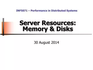
Tracks Arm movement Arm assembly Components of a Disk Spindle • The platters spin (say, 90 rps). • The arm assembly is moved in or out to position a head on a desired track. • Tracks under heads make a cylinder(imaginary!). • Only one head reads/writes at any one time. Disk head Sector Platters • Block size is a multiple of sector size (which is fixed).
Inner Track Outer Track Sector Head Arm Platter Actuator Disk Device Terminology • Several platters, with information recorded magnetically on both surfaces (usually) • Bits recorded in tracks, which in turn divided into sectors (e.g., 512 Bytes) • Actuator moves head (end of arm,1/surface) over track (“seek”), select surface, wait for sector rotate under head, then read or write • “Cylinder”: all tracks under heads
{ Platters (12) Disk Head, Arm, Actuator Spindle Arm Head Actuator
Disk Device Performance Inner Track Outer Track Sector Head Controller Arm Spindle Platter Actuator
Physical disk organization • To read or write, the disk head must be positioned on the desired track and at the beginning of the desired sector • Seek time is the time it takes to position the head on the desired track • Rotational delay or rotational latency is the additional time its takes for the beginning of the sector to reach the head once the head is in position • Transfer time is the time for the sector to pass under the head
Physical disk organization • Access time = seek time + rotational latency + transfer time • Efficiency of a sequence of disk accesses strongly depends on the order of the requests • Adjacent requests on the same track avoid additional seek and rotational latency times • Loading a file as a unit is efficient when the file has been stored on consecutive sectors on the same cylinder of the disk
Example: Two single-sector disk requests • Assume • average seek time = 10 ms • average rotational latency = 3 ms • transfer time for 1 sector = 0.01875 ms • Adjacent sectors on same track • access time = 10 + 3 + 2*(0.01875) ms = 13.0375 ms • Random sectors • access time = 2*(10 + 3 + 0.01875) ms = 26.0375 ms
Disk Scheduling (Cont.) • Several algorithms exist to schedule the servicing of disk I/O requests. • We illustrate them with a request queue (0-199). 98, 183, 37, 122, 14, 124, 65, 67 Head pointer 53
FCFS Illustration shows total head movement of ______cylinders.
SSTF • Selects the request with the minimum seek time from the current head position. • SSTF scheduling is a form of SJF scheduling; may cause starvation of some requests.
SSTF (Cont.) total head movement of ______cylinders
SCAN • The disk arm starts at one end of the disk, and moves toward the other end, servicing requests until it gets to the other end of the disk, where the head movement is reversed and servicing continues. • Sometimes called the elevator algorithm.
C-SCAN • Provides a more uniform wait time than SCAN. • The head moves from one end of the disk to the other. servicing requests as it goes. When it reaches the other end, however, it immediately returns to the beginning of the disk, without servicing any requests on the return trip. • Treats the cylinders as a circular list that wraps around from the last cylinder to the first one.
C-LOOK • Version of C-SCAN • Arm only goes as far as the last request in each direction, then reverses direction immediately, without first going all the way to the end of the disk.
Selecting a Disk-Scheduling Algorithm • SSTF is common and has a natural appeal • SCAN and C-SCAN perform better for systems that place a heavy load on the disk. • Performance depends on the number and types of requests. • Requests for disk service can be influenced by the file-allocation method. • The disk-scheduling algorithm should be written as a separate module of the operating system, allowing it to be replaced with a different algorithm if necessary. • Either SSTF or LOOK is a reasonable choice for the default algorithm.