Download
1 / 22
220 likes | 366 Vues
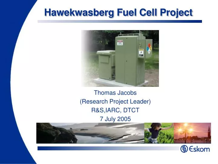
Hawekwasberg Fuel Cell Project. Thomas Jacobs (Research Project Leader) R&S,IARC, DTCT 7 July 2005. Agenda. Background Literature study (fuel cells) History Basic operation Benefits Lifecycle costing Equipment GenCore 5T fuel cell Cordex rectifier Why Hawekwasberg?

E N D
Hawekwasberg Fuel Cell Project Thomas Jacobs (Research Project Leader) R&S,IARC, DTCT 7 July 2005
Agenda • Background • Literature study (fuel cells) • History • Basic operation • Benefits • Lifecycle costing • Equipment • GenCore 5T fuel cell • Cordex rectifier • Why Hawekwasberg? • System integration • Research timelines • Alternative Energy Storage Technologies • Hawekwasberg trialsite project • Eskom Telecoms involvement
Background OBJECTIVE Evaluation of the alternative energy storage technologies for utility stationary standby power applications. WORKING GROUP MEMBERS • Thomas Jacobs (R&S) • Johan Beukes (R&S) • Leon Drotsché (Dx) • Anthony Sheerin (Tx) • Bathathu Jonga (Tx) • Philip Groenewald (R&S) • Christo van Zyl (Dx) KEY QUESTIONS • Ideal energy storage device requirements? • What benefits do these alternative technologies offer and how can they be integrated in the business processes? • How do these devices compare to technologies currently in use ito life cycle issues? • How do the load profiles at existing substations and other sites look?
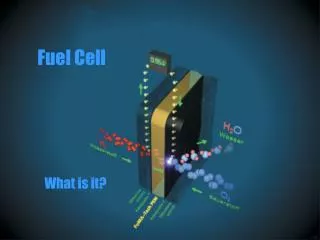
Fuel cells • Electrochemical energy conversion device • H2 + O2 = e- + heat + H2O => “Green” energy Analogies -> Fuel cell vs. • Battery: Does not require recharge and does not run flat • Generator: Produce electricity as long as fuel and oxidant available
Fuel cells (cont) • Basic operation of fuel cells • Fuel electrode (anode), Oxidant electrode (cathode) and ion-selective membrane (ISM) • Ions penetrate ISM and e- flows through electric circuit • Independent scaling of energy section (fuel cylinders) and power section (cell stacks)
Fuel cells (cont.) • General advantages • Very efficient (35-45%) vs Internal combustion engine (15% ave -35% max) • High energy density (1,3 kW / liter – PEMFC) • Simplicity – few moving parts – low maintenance • Environmental friendliness (No harmful emissions) • Very quiet • Scalable / modular • Independent scaling of power and energy • Power quality (Stable and predictable) • Waste heat recoverability (Co-generation applications) • Fuel flexibility (H2, LPG, Methanol, etc) • Economical
Lifecycle costing 48V system LCC comparison
Why Hawekwasberg? • Site selection criteria: • Adequate space • Security • Easy site access (close to city / town) • Remote communications • Site not environmentally sensitive • Extreme environmental conditions • 50% + loading
Equipment – fuel cell • Plugpower GenCore 5T Fuel cell • Power output: 0 - 5kW • Water output: 2 liters per hour • Voltage range: -46 to -56Vdc (adjustable) • Output current: 0 – 109A • Fuel: 99.95% hydrogen • Operating temperature: -40 to 46°C (Outdoor unit) • Noise: <60dB @ 1m • Weight: 230kg • Optional fuel storage system with 6x50 liters cylinders • Set via laptop / PC with user friendly MMI • Remote monitoring, diagnostics and alarming facilities • Internal VRLA battery
Equipment – fuel cell (cont.) Block diagram
Equipment – fuel cell (cont.) Fuel cell stack
Field experience – fuel cell Since 2003 approximately 120 systems have shipped to customers Verizon – Albany, New York FDT/Orange - Elgin, Scotland > 3463 starts since Feb 04 > 217 starts since December > 946 total hours of runtime > 3974 total hours of runtime Installations are providing backup power for telecommunication networks (wireline and wireless) and industrial uninterruptible power supply applications
Equipment - rectifier • Rectfier system • 1 x CXCR system controller • 3 x 48V / 21A, CXRC switched mode rectifiers • Convection cooled • Remote control and setting functionality (internal modem)
System integration Existing system configuration Standing drain: Load A = 35A Load B = 30A
System integration (cont.) Site layout and equipment placement
Research Timelines PHASE 1: Literature study Load profile studies PHASE 2: Test system acquisition and installation 50V Plug Power Fuel Cell 125V Plug Power Fuel Cell PHASE 3: Preparation of experiment Build, install & commission MiniQPS MiniQPS GUI enhancements MiniQPS firmware upgrade PHASE 4: Experiments 50V FC Startup tests 125V FC Startup & Load Profile tests PHASE 5: Trial site Selection & designs Installation, commissioning & tests
Research Timelines (cont.) Hawekwasberg Trialsite
Hawekwasberg Fuel Cell Project The END Thank you Industry Association Resource Centre “Your Technology Partner”