Download
1 / 41
760 likes | 1.63k Vues
Texture Components and Euler Angles. 27- 750 Texture , Microstructure & Anisotropy A.D . (Tony) Rollett. Last revised: 12 th Jan. 2014. Lecture Objectives. Show how to convert from a description of a crystal orientation based on Miller indices to matrices to Euler angles.

E N D
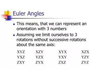
Texture Components and Euler Angles 27-750 Texture, Microstructure & Anisotropy A.D. (Tony) Rollett Last revised: 12thJan. 2014
Lecture Objectives • Show how to convert from a description of a crystal orientation based on Miller indices to matrices to Euler angles. • Give examples of standard named components and their associated Euler angles. • The overall aim is to be able to describe a texture component by a single point (in orientation space, which is parameterized with some set of coordinates such as Euler angles) instead of needing to draw the crystal embedded in a reference frame. • Homework exercises will be converting Miller indices to Euler angles. Obj/notation AxisTransformation Matrix EulerAngles Components
(hkl)[uvw], Miller Index Definition of a Crystal Orientation • We use a set of three orthogonal (mutually perpendicular) directions as the reference frame. Mathematicians set up a basis set of unit vectors called e1 e2 and e3. All directions can then be described as (linear) combinations of the three basis vectors. See the Supplemental Slides for explanations of vectors and unit vectors. • In many cases we use the metallurgical names Rolling Direction (RD) // e1, Transverse Direction (TD) // e2, and Normal Direction (ND) // e3. • We then identify a crystal (or plane normal) parallel to 3rd axis (ND) and a crystal direction parallel to the 1st axis (RD), written as (hkl)[uvw]. The second axis is then completely specified by the other two. This situation is sometimes referred to as “biaxial texture”, to distinguish it from “uniaxial texture” in which only one crystal axis of each grain is aligned with the specimen. • In thin films, we must still use a reference frame with 3 axes but very often, only the normal direction (ND) or film-plane-normal matters because only one crystal direction is aligned with the ND, which is the uniaxial texture referred to above. Be aware, however, that an epitaxial thin film can be biaxially aligned to the substrate in which case all 3 axes are relevant. This latter case is important to High Temperature Superconductor processing, for example.
Orientation specification via (hkl)[uvw] ≡Z≡e3 ∕ ∕ Z (hkl) ≡Y≡e2 ≡X≡e1 [uvw] ∕ ∕ X Obj/notation AxisTransformation Matrix EulerAngles Components
Active versus Passive Rotations • Before we discuss the details of how to calculate orientation matrices, it is a good idea to summarize the difference between “active” and “passive” rotations, as mathematicians know them. • In materials science, we are mostly concerned with describing anisotropic properties of crystals and the aggregate anisotropy of polycrystalline materials, for which it is convenient to use tensors to describe those properties. • For tensor quantities, we commonly need their coefficients in either the sample frame or the crystal frame. For this we use “transformations of axes”, which are “passive rotations”, in the sense that the two frames share a common origin and differ by only a (proper) rotation. The tensor quantities do not rotate in real space, however. • In solid mechanics, however, it is more typical to need to describes the motions of objects. Certain motions are just rotations and one can think of rotating a vector, for example, about the origin, in which case one is describing an “active rotation”. Some object is rotated about the origin and moves through the frame. • For all work in texture we will consistently use axis transformations, a.k.a. passive rotations.
Rotation of axes in the (2D) plane:x, y = old axes; x’,y’ = new axes v q N.B. Passive Rotation/ Transformation of Axes Obj/notation AxisTransformation Matrix EulerAngles Components
Definition of an Axis Transformation:ê= old axes;ê′= new axes We transform the coefficients of, e.g., a vector, v, from one set of axes to another v ê3 From Sample to Crystal (primed) ê’3 ê’2 ê2 ê’1 ê1 Obj/notation AxisTransformation Matrix EulerAngles Components
Geometry of {hkl}<uvw> Sample to Crystal (primed) ^ ^ Miller indexnotation oftexture componentspecifies directioncosines of crystaldirections // tosample axes. Form the second axis from the cross-product of the 3rd and 1st axes. e’3 e3 // (hkl) [001] [010] ^ e’2 ^ ^ e2 // t ^ e1 // [uvw] ^ e’1 t = hklxuvw [100] Obj/notation AxisTransformation Matrix EulerAngles Components
Form matrix from Miller Indices Basic idea: we can construct the complete rotation matrix from two known, easy to determine columns of the matrix. Knowing that we have columns rather than rows is a consequence of the sense of rotation, which is equivalent to the direction in which the axis transformation is carried out. Obj/notation AxisTransformationMatrixEulerAngles Components
(Bunge) Euler Angle Definition [Bunge] • The three reference axes are labeled as X, Y & Z; also commonly known as ND, RD, and TD. • The three crystal axes are labeled as X’, Y’ & Z’ ; also commonly known as [100], [010] & [001] in cubic crystals. • The reference (sample) frame is labeled as “KA” in the figure, and the crystal frame as “KB”. • Each diagram shows successive rotations, more properly thought of as transformations of axes. Obj/notation AxisTransformation Matrix EulerAngles Components
e3=Zsample=ND e’3= 3rd position (final) [001] 2nd position [010] zcrystal=e3’’’= 1st position f1 ycrystal=e2’’’ e”3 e”2 f2 e’2 e2=Ysample=TD RD Crystal xcrystal=e1’’’ [100] F TD e’1 =e”1 e1=Xsample=RD Sample Axes Euler Angles, Animated Obj/notation AxisTransformation Matrix EulerAngles Components
Cube Texture (001)[100]: cube-on-face • Observed in recrystallization of fcc metals • The three crystal axes, <001>, are parallel to the three sample axes, i.e. ND, RD, and TD directions. [001] [100] [0-10] Obj/notation AxisTransformation Matrix EulerAnglesComponents
Sharp Texture (Recrystallization) • Figure on the left shows the {001} pole figures (PFs) for this texture component: maxima correspond to {100} poles in the standard stereographic projection aligned with the sample axes. Note that this pole figure could not be measured experimentally unless transmission and reflection methods were to be combined because the reflections on the edge of the PF cannot be detected (see lecture on PF measurement). Obj/notation AxisTransformation Matrix EulerAnglesComponents
Euler angles of Cube component • The Euler angles for this component are simple, and yet not so simple! • The crystal axes align exactly with the specimen axes, therefore all three angles are exactly zero: (f1, , f2) = (0°, 0°, 0°). • Orientation Matrix: • Rodrigues vector: [0,0,0] • Unit quaternion: [0,0,0,1] • As an introduction to the effects of crystal symmetry: consider aligning [100]//TD, [010]//-RD, [001]//ND. This is evidently still the cube orientation, but the Euler angles are (f1,,f2) = (90°,0°,0°)! Obj/notation AxisTransformation Matrix EulerAnglesComponents
{110}<001>: the Goss Component • This type of texture is known as Goss Texture and occurs as a Recrystallization texture for FCC materials such as Brass, … • In this case the (011) plane is oriented towards the ND and the [001] inside the (011) plane is along the RD. ND (110) TD [001] [100] RD Obj/notation AxisTransformation Matrix EulerAnglesComponents
{110}<001>: cube-on-edge • In the 011 pole figure, one of the poles is oriented parallel to the ND (center of the pole figure) but the other ones will be at 60° or 90° angles but tilted 45° from the RD! (Homework: draw the (111) pole figure by hand.) ND (110) TD [001] [100] RD {110}
Euler angles of Goss component • Matrix: • Rodrigues vector: [ tan(22.5°), 0 , 0 ] • Unit quaternion:[ sin(22.5°) , 0, 0, cos(22.5°)] • Note that, since there is only one non-zero Euler angle, the rotation axis is obvious by inspection, i.e. the x-axis. For more general cases, the rotation axis has to be calculated. • The Euler angles for this component are simple, and yet other variants exist, just as for the cube component. • Only one rotation of 45° is needed to rotate the crystal from the reference position (i.e. the cube component) to (011)[100]; this happens to be accomplished with the 2nd Euler angle. • (f1,,f2) = (0°,45°,0°). • Other variants will be shown when symmetry is discussed. Obj/notation AxisTransformation Matrix EulerAnglesComponents
Brass component • This type of texture is known as Brass Texture and occurs as a rolling texture component for materials such as Brass, Silver, and Stainless steel. Obj/notation AxisTransformation Matrix EulerAnglesComponents
Brass component, contd. • The associated (110) pole figure is very similar to the Goss texture pole figure except that it is rotated about the ND. In this example, the crystal has been rotated in only one sense (anticlockwise). (100) (111) (110) Obj/notation AxisTransformation Matrix EulerAnglesComponents
{110}<112> Brass component • Think of rotating the Goss component around the ND. In this example, the xtal has been rotated in both senses (two variants).
Brass component: Euler angles • The brass component is convenient because we can think about performing two successive rotations: • 1st about the ND, 2nd about the new position of the [100] axis. • 1st rotation is 35° about the ND; 2nd rotation is 45° about the [100]. • (f1,,f2) = (35°,45°,0°). Obj/notation AxisTransformation Matrix EulerAnglesComponents
Euler Angle Conventions • An inconvenient fact is that the definition of Euler angles that we have given so far is not unique. • Many other variants not only exist but have names and are in regular use! • The differences between the conventions lie in the choice of the rotation axes (generally only the second axis) and the sense of rotation. • Some of the commonly used conventions are Bunge, Kocks, Roe and Canova* (in approximate order of decreasing popularity). • For the purposes of this course we will only use the Bunge convention. *You will find Canova angles inside the computer code LApp
Meaning of Bunge Euler angles • In the Bunge convention, the first two angles, f1 and F, tell you the position of the [001] crystal direction relative to the specimen axes. • Think of rotating the crystal about the ND (1st angle, f1); then rotate the crystal out of the plane (about the [100] axis, F); • Finally, the 3rd angle (f2) tells you how much to rotate the crystal about [001]. Obj/notation AxisTransformation Matrix EulerAngles Components
Meaning of Roe Euler angles • In the Roe convention, the first two angles, and Q, tell you the position of the [001] crystal direction relative to the specimen axes. • Then think of rotating the crystal about the ND or 001 or z-axis (1st angle, ); then rotate the crystal out of the plane (about [010], or the y-axis, Q); • Finally, the 3rd angle (F)tells you how much to rotate the crystal about [001]. Obj/notation AxisTransformation Matrix EulerAngles Components
Meaning of Kocks Euler angles • In the Kocksconvention, which is almost the same as the Roe convention with the exception of the third angle, the first two angles, and Q, tell you the position of the [001] crystal direction relative to the specimen axes. • Then think of rotating the crystal about the ND or 001 or z-axis (1st angle, ); then rotate the crystal out of the plane (about [010], or the y-axis, Q); • Finally, the 3rd angle ()tells you how much to counter-rotate the crystal about [001]. Here’s the difference between Roe and Kocks - the last angle is a negative or clockwise rotation about 001, instead of a positive or counter-clockwise rotation. Obj/notation AxisTransformation Matrix EulerAngles Components
Kocks Euler Angles:Ship Analogy [Kocks, Tomé, Wenk] • Analogy: position and the heading of a boat with respect to the globe. Latitude (Q) and longitude (y) describe the position of the boat; third angle describes the heading (f) of the boat relative to the line of longitude that connects the boat to the North Pole. Kocks vs. Bunge angles:to be explained later! Obj/notation AxisTransformation Matrix EulerAngles Components
Euler Angle Definitions [Kocks, Tomé, Wenk] Bunge and Canova are inverse to one anotherKocksand Roe differ by sign of third angleBunge rotates about x’, Roe/Kocksabout y’(2nd angle) Obj/notation AxisTransformation Matrix EulerAngles Components
Euler Angle Conversions Obj/notation AxisTransformation Matrix EulerAngles Components
Complete orientations in the Pole Figure f1 (f1,,f2) ~ (30°,70°,40°). Note the loss ofinformationin a diffractionexperiment if each set of poles from a single component cannot be related to one another. f2 F f1 F f2 [Bunge] Obj/notation AxisTransformation Matrix EulerAngles Components
Complete orientations in the Inverse Pole Figure [Bunge] Think of yourself as an observer standing on the crystal axes, and measuring where the sample axes lie in relation to the crystal axes. Obj/notation AxisTransformation Matrix EulerAngles Components
Summary • Conversion between different forms of description of texture components described. • Physical picture of the meaning of Euler angles as rotations of a crystal given. • Miller indices are descriptive, but matrices are useful for computation, and Euler angles are useful for mapping out textures (to be discussed).
In-Class Exercises: 1 • Draw three orthogonal axes to represent the reference frame. Draw a unit cube to represent a crystal such the that <100> directions are aligned with the {x,y,z} axes. Explain that there are several alternative labels for such sets of axes or frames-of-reference, such as {RD,TD,ND}. Distinguish between the use of {} to denote a family of plane normals and {} to denote a set of objects (which may, or may not, constitute a group). Explain that this alignment is called the “cube component”. • Starting with the reference frame, also called the sample frame, sketch the 3 successive rotations that correspond to the (Bunge) Euler angles, {f1, F, f2}. Label the axes of rotation for each one. Explain that it is permissible to describe this process in terms of rotations about the crystal z axis, then the x axis, then the z axis again. • Draw the sample frame, with labels, and then draw a unit cube with one edge parallel to the sample x axis and rotated by 45° about this axis. State that this is a graphical representation of the texture component known as “Goss”. Identify the Miller indices of the three crystal directions parallel to {RD, TD, ND} as {100,011,0-11}.
In-Class Exercises: 2 • For the Goss component shown previously, explain that the Euler angles that parameterize this texture component are {0,45,0} (in degrees). Refer to the previous explanation of the definition of the Bunge Euler angles to do this. • For the same Goss component, draw the {110} pole figure. Hint: a simple way to do this is to find a diagram of the stereographic projection for cubic materials with 110 in the center of the figure; rotate it until a <100> direction is aligned pointing to the right. In all our work we will align the x axis of a Cartesian reference frame pointing to the right, just as in standard mathematical plots, and the y axis pointing up. • For the same Goss component, introduce the rotation matrix. Setting aside its properties as an orthogonal matrix for the time being, explain how one can construct it as a 2x2 45° rotation matrix, which can then be embedded in a 3x3 matrix to represent the 45° rotation about the x axis.
In-Class Exercises: 3 • Introduce the Brass component by using the same 110 stereographic projection as before but rotating it so that, instead of having, say, 001//RD, now we have -112//RD. Show that the angle required to rotate from Goss to Brass is approximately 35°. Show that this rotation is about the center of the projection, i.e. 110. • Picking up from the previous exercise, show that the combination of the 45° rotation about x to arrive at the Goss component, combined with the 35° rotation about 110 means that we can describe the Brass component with Euler angles {35,45,0}. • Show, again with the aid of the projection, that the 3 crystal directions parallel to the sample frame are {-112, 1-11, 110}. Check that these form a right-handed set! • Draw the definition of the Roe Euler angles. Explain the differences between this definition and the Bunge definition. • Draw the definition of the Kocks convention for Euler angles. Explain the differences between this definition and the Bunge definition. • List the conversions between the different definitions of Euler angles.
In-Class Exercises: 4 • Setting aside the precise definition of a pole figure for the time being, sketch a pole figure with the sample X pointing to the right, the Y up and the Z in the center. (Later on we will discuss the confusing practice of drawing pole figures with RD up and TD to the right.) Sketch the successive rotations that correspond to the 3 (Bunge) Euler angles. • Sketch an inverse pole figure with the crystal x (i.e. 100) pointing to the right, the y (010) up and the z (001) in the center. Sketch the successive rotations that correspond to the 3 (Bunge) Euler angles. You will find it easier to start with the last angle, f2, and work backwards. • Anticipating the next lecture, discuss how to use the information about hkl//Z and uvw//X to construct a set of 3 mutually orthogonal unit vectors as a preliminary to obtaining an orientation matrix.
Supplementary Slides • The following slides provide supplementary information on Miller indices, the dot (scalar) product and direction cosines.
Miller Indices • Cubic system: directions, [uvw], are equivalent to, and parallel to plane normals with the same indices, (hkl). • Miller indices for a plane specify reciprocals of intercepts on each axis.
Miller <-> vectors • Miller indices [integer representation of direction cosines] can be converted to a unit vector, n, by dividing by the square root of the sum of the squares: {similar for [uvw]}. This is known as normalization.
Miller Index Definition of a Texture Component • The commonest method for specifying a texture component is the plane-direction. • Specify the crystallographic plane normal that is parallel to the specimen normal (e.g. the ND) and a crystallographic direction that is parallel to the long direction (e.g. the RD). (hkl) || ND, [uvw] || RD, or (hkl)[uvw]
Dot Product • Given two vectors, a and b, the dot product, a•b is a scalar quantity that is equal to the product of the magnitudes (lengths) of the vectors, multiplied by the cosine of the angle between them:a•b = a bcos • If both vectors are unit vectors then the dot product is equal to the cosine of the angle. • In index form, a•b = aibi. • Given a set of unit vectors defining an axis system, ex, ey, ez,a vector can be defined on that system by taking the dot product with each axis vector in turn, e.g.:ax = a•ex
Direction Cosines • Definition of direction cosines: • The components of a unit vector are equal to the cosines of the angle between the vector and each (orthogonal, Cartesian) reference axis. • We can use axis transformations to describe vectors in different reference frames (room, specimen, crystal, slip system….)