Download
1 / 17
270 likes | 733 Vues
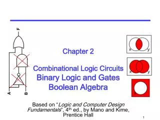
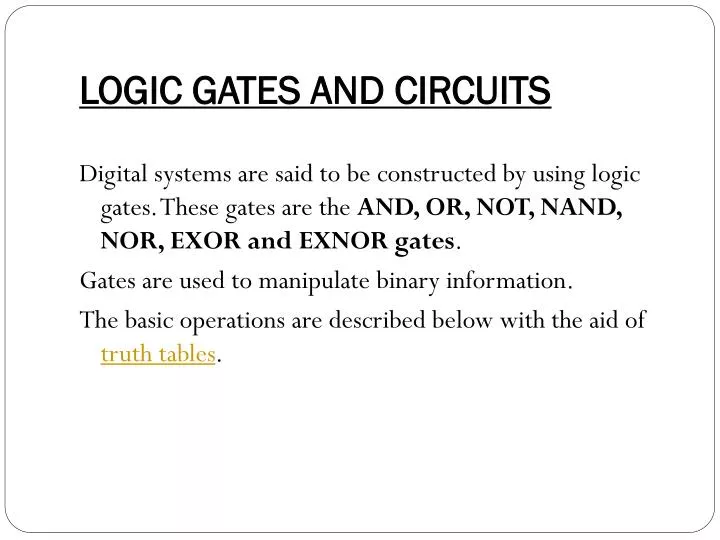
LOGIC GATES AND CIRCUITS. Digital systems are said to be constructed by using logic gates. These gates are the AND, OR, NOT, NAND, NOR, EXOR and EXNOR gates . Gates are used to manipulate binary information. The basic operations are described below with the aid of truth tables. Truth Table

E N D
LOGIC GATES AND CIRCUITS Digital systems are said to be constructed by using logic gates. These gates are the AND, OR, NOT, NAND, NOR, EXOR and EXNOR gates. Gates are used to manipulate binary information. The basic operations are described below with the aid of truth tables.
Truth Table • The Truth table consist of all input combinations and corresponding output state. • The input-output relationship of the binary variables for each gate can be represented in tabular form by a truth table.
AND GATE The AND gate is an electronic circuit that gives a high output (1) only if all its inputs are high. A dot (.) is used to show the AND operation i.e. A.B. Bear in mind that this dot is sometimes omitted i.e. AB
OR GATE The OR gate is an electronic circuit that gives a high output (1) if one or more of its inputs are high. A plus (+) is used to show the OR operation.
NOT GATE The NOT gate is an electronic circuit that produces an inverted version of the input at its output. It is also known as an inverter. If the input variable is A, the inverted output is known as NOT A. This is also shown as A', or A with a bar over the top, as shown at the outputs.
NAND GATE This is a NOT-AND gate which is equal to an AND gate followed by a NOT gate. The outputs of all NAND gates are high if any of the inputs are low. The symbol is an AND gate with a small circle on the output. The small circle represents inversion.
NOR GATE This is a NOT-OR gate which is equal to an OR gate followed by a NOT gate. The outputs of all NOR gates are low if any of the inputs are high. The symbol is an OR gate with a small circle on the output. The small circle represents inversion.
XOR OR EOR The 'Exclusive-OR' gate is a circuit which will give a high output if either, but not both, of its two inputs are high. An encircled plus sign () is used to show the EOR operation.
X-NOR OR E-NOR The 'Exclusive-NOR' gate circuit does the opposite to the EOR gate. It will give a low output if either, but not both, of its two inputs are high. The symbol is an EXOR gate with a small circle on the output. The small circle represents inversion.
NOTES- • The NAND and NOR gates are called universal functions since with either one the AND and OR functions and NOT can be generated. • A function in sum of products form can be implemented using NAND gates by replacing all AND and OR gates by NAND gates. • A function in product of sums form can be implemented using NOR gates by replacing all AND and OR gates by NOR gates.
PROBLEMS- implement NOT, AND, and OR gate by using NAND and NOR gates ?
BOOLEAN ALGEBRA The relation between the inputs and the outputs of a gate can be expressed mathematically by means of the boolean expression.
DeMorgan's Law The most important logic theorem for digital electronics, this theorem says that any logical binary expression remains unchanged if we • Change all variables to their complements. • Change all AND operations to ORs. • Change all OR operations to ANDs. • Take the complement of the entire expression.
Demorgan’s expression NOTE- • DeMorgans Laws are applicable for any number of variables.