Download
1 / 14
150 likes | 371 Vues
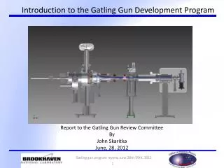
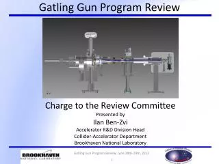
Gatling Gun Beam Diagnostics and Instrumentation. David Gassner Gatling Gun Review June 28, 2012. Outline. Phase 1 diagnostics p hilosophy: Provide core diagnostics for the first beams, current and profile. Overview Beam and machine parameters, challenges Beam transport layout

E N D
Gatling Gun Beam Diagnostics and Instrumentation David Gassner Gatling Gun Review June 28, 2012
Outline Phase 1 diagnostics philosophy: Provide core diagnostics for the first beams, current and profile. • Overview • Beam and machine parameters, challenges • Beam transport layout • Current Monitors • Beam Integrating Current Transformer (ICT) • Cable Current Monitors • Beam Profile Monitors • YAG Screen Viewer • Halo Detector • Future Upgrades • Beam Position Monitor • Fast Current Transformer (FCT) • Pepper Pot • Summary
Beam and Machine Parameters Electron Beam Parameters • Initial tests; 2 cathodes, 1 Hz operations • 2 beams ~ 15mm full with diameter at the profile monitor • 3.5nC charge per bunch • 1.5nS FWHM bunch length • Energy = 220 KeV Challenges for instrumentation • 250kV potential voltages • Sensitive photocathodes • Vacuum 10-12 Torr range • Bake out compatibility to 400C • Outgassing and desorption concerns
Beam Transport Layout Profile Monitor Ceramic Break for HV Beam Current Transformer 230kV 230kV Inside Collector cage Gun Cathodes Halo Detector Combiner Diagnostics station is grounded Collector
Beam Current Transformer Beam Line Device: Bergoz off-the-shelf Integrating Current Transformer (ICT) 178mm ID, fits over 6” CF flange Mounted around dedicated commercial ceramic break GG transport beam pipe 3.67” ID Removable copper image current shroud Plan to bake beam pipe to 400C, will need cooling to ensure ICT does not exceed 150C. Side View Detailed mechanical design not complete Similar installation at C-AD
Beam Current Transformer Electronics Bergoz - Beam Charge Monitor (BCM) Integrate-Hold-Reset (IHR) electronics - Measure individual bunches & bunch trains - Integration gate width adjustable 0.1us to 7us Noise <1pC beam charge Calibrated 10kHz max individual bunch rate measurement Planned beam intensity/bunch range 100pC – 3.5nC BCM-IHR Timing diagram
Cable Current Monitors Beam makes 2 bends from gun photocathode to beam ICT Potential for measuring: - Transport efficiency between gun, collector, and ground. - Beam losses - Cathode QE Monitor current pulses (3.5nC, 1.5nS) in cables at several locations. ICT Reasonable to pursue this measurement? These measurement present accuracy challenges (noise, matching, HV, etc…) Need to look at details, setting up some tests.
Profile Monitor Profile Monitor Ceramic Break for HV Current Transformer 230kV 200kV Inside Collector cage Gun Cathodes Halo Detector Combiner Grounded region Collector
Transverse Profile Monitor – YAG:Ce Screen Transverse beam size ~15mm round diameter Lens and CCD Camera Destructive measurement (low power) YAG screen normal to beam Copper mirror at 450 downstream Virtual Resolution Target Linear Magnetic Actuator (2 position) Transfer Engineering Inc. PMM-Lite model 400C bake-out YAG:Ce Screen 5cm diameter (4.5cm active) Thin coating on upstream side to bleed off charge Thickness = Few hundred microns GigE CCD camera 3-motor lens, zoom, focus, iris. Virtual target for optical <100 microns optical resolution Removable Optics Box Semitransparent mirror Electron Beam Optics Box Courtesy Radiabeam
Transverse Profile Monitor – YAG:Ce Desorption Concern Q: Will we be able to see an image on the YAG screen without ruining the cathodes? Pressure Rise vs. Current on YAG screen Igor Alexander, B2/Mainz A: If our double bend inhibits ion movement similar to the 270o bend at Mainz then we hope to tolerate a few uA’s on the YAG screen and not damage the cathodes. Pressure doubles with 3uA on YAG, in 10-8 torr range Mott Pol. Mainz PKAT Test Source Gun (~10-11 torr) 270o bend YAG Screen (~10-8torr) Source: B2/Mainz
Halo Detector Profile Monitor Halo Detector Current Transformer 230kV 230kV Inside Collector cage Gun Cathodes Grounded region Combiner Ceramic Break for HV Collector
Halo Detector Profile Monitor – Upstream of Collector Halo Detectors Quad split (230kV) Isolated molybdenum jaws - Quad configuration - Need shield from collector (not designed yet) Electronics: Gated integrator Signal processing on HV platform: Fiber optic connection to transfer data Protect electronics from arcs. E-Lens Quad Scraper Collector 230kV Electron Repeller (260kV) Ceramic Break Grounded shield Raw signals from similar E-Lens Quad Halo Detector, beam offset (green & red)
Future Upgrades Beam Position Monitor Measure bunch center of mass positions (when combiner field is rotating) Need space in beam transport for pick-up High temperature (400C) pick-up design Side View Fast Current Transformer (can be installed along side of ICT) Measure individual bunch charge in bunch trains 300ps rise time, 1GHz bandwidth Calibrated measurement, Fast scope DAQ Track charge evolution (QE) for each cathode Toroid widths ICT = 32mm FCT = 22mm • Pepper Pot Emittance Measurement • Apreliminary design: Normalized emittance: xn/yn= 20.5µm/20.1µm • Slit width: 1 mm, slit space: 1.5 mm (~ 5 beamlets) • Drift space: 0.1 m < L < 0.3 m upstream of YAG profile monitor • Thickness: 1 mm (Tungsten, SS, or copper) • Use horizontal and vertical slits one on upper part, one on lower part of the mask.
Summary • Core Diagnostic for Phase 1 • Proof of principle, 2 cathodes, 1Hz operation • YAG:Ce Screen (Transverse profile, destructive, low power) • Quad Scraper (Near collector, halo monitor) • Current transformers (Bunched beam, and on cables) • Future Upgrades • More cathodes, higher frequency bunch trains • Beam Position Monitor (Non-destructive, fast) • Fast Current Transformer (Bunch charge in long trains) • Pepper Pot (Emittance, destructive)