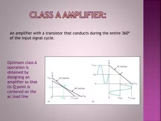
Download
1 / 19
270 likes | 637 Vues
Class D Power amplifier -----using ADS. Song lin @utk June30. Outline. Why select Class D? Compare different device Simple Class D architecture Load-pull to give out Zout Matching and simulation results of ideal narrow band Class D PA Broad band matching. Why Class D?.

E N D
Class D Power amplifier-----using ADS Song lin @utk June30
Outline • Why select Class D? • Compare different device • Simple Class D architecture • Load-pull to give out Zout • Matching and simulation results of ideal narrow band Class D PA • Broad band matching
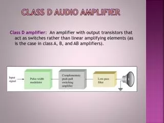
Why Class D? • Class D PA works in the switching mode, with a square wave voltage and a half wave rectified sine wave of current. • In its ideal switching mode, when Vds<>0, Ids=0; when Ids<>0,Vds=0. • Class D PA can achieve very high frequency close to 100%. Although it is very nonlinear, we still can use the LINC technique to kill the IMD product.
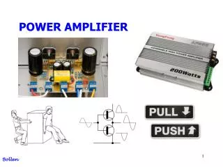
Compare the device(I) • For high frequency, ----- the higher the better • For high on/off switching speed,----- the shorter the better • For high efficiency, the on-resistance of a switching device must be as low as possible to minimize the power dissipation in the switches during the positive half cycle.----- Rs is the smaller the better. • For high Power output, ----- BV(beake down voltage) the higher the better • For high Gain, ----- the bigger the better • For power dissipate,----- the small the better
Compare the device(II) Conclusion: Also for the wide band application, we should chose the component whose Zout and Zin has very little variety in some frequency range. I suggest to use the MRF282SR1.-----N-channel Enhancement-Mode Lateral MOSFETs
Narrow band input and output matching and simulation results
Wide band matching using coaxial A conventional design allows the coaxial transformer to transform the impedance to obtain a match the low end of the band, then add additional low-pass matching sections to lower the impedance at the upper band edge.
The problem remain: • The Class D PA need a resonator tank to pull out the fundamental signal, to filter out the third time signal, so I decide to divide the band into 3 parts, one from 30 to 88 MHz; 88MHz to 200MHz; 200MHz to 500MHz. We can separate the signals by filter bank. • For the real device, the Rs isn’t very small, so the efficiency can’t be so high. Because of the , the Vds and some overlap with Ids, it also kill some efficiency. • To achieve better performance at low frequency band, I have to increase the Vgg. • ADS is very hard to converge when simulation.