Download
1 / 26
270 likes | 546 Vues
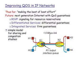
Improving Availability in Multilayer Switched Networks. Multilayer Network Design. Access. Distribution. Backbone. Core. Building Block Additions. Server Farm. WAN. PSTN. Internet. Layer-2 Mode Load Balancing. Layer-3 Mode Load Balancing. HSRP 1 A. HSRP 1 s. HSRP 2 s. HSRP 2 A.

E N D
Multilayer Network Design Access Distribution Backbone Core Building Block Additions Server Farm WAN PSTN Internet
Layer-2 Mode Load Balancing Layer-3 Mode Load Balancing HSRP 1A HSRP 1s HSRP 2s HSRP 2A VLAN Trunk A&B VLAN Trunk A&B VLAN Trunk A&B VLAN Trunk A&B Fwd VLAN B Block VLAN A VLAN Trunk A&B Fwd VLAN A Block VLAN B Forward VLAN B Forward VLAN A VLAN A and B VLAN A and B Multi-VLAN Load Balancing Methods
First Hop Redundancy Schemes • Hot Standby Router Protocol (HSRP) • Cisco informational RFC 2281 ( March 1998) • Virtual Router Redundancy Protocol (VRRP) • IETF Standard RFC 2338 (April 1998) • Gateway Load Balancing Protocol (GLBP) • Cisco designed, load sharing, patent pending
HSRP • A group of routers function as one virtual router by sharing ONE virtual IP address and ONE virtual MAC address • One (Active) router performs packet forwarding for local hosts • The rest of the routers provide “hot standby” in case the active router fails • Standby routers stay idle as far as packet forwarding from the client side is concerned
IP: 10.0.0.3 MAC: aaaa.aaaa.aa03 GW: 10.0.0.10 ARP: 0000.0c07.ac00 IP: 10.0.0.1 MAC: aaaa.aaaa.aa01 GW: 10.0.0.10 ARP: 0000.0c07.ac00 IP: 10.0.0.252 MAC: 0000.0cde.f123 vIP: vMAC: IP: 10.0.0.253 MAC: 0000.0C78.9abc vIP: vMAC: IP: 10.0.0.254 MAC: 0000.0c12.3456 vIP: 10.0.0.10 vMAC: 0000.0c07ac00 IP: 10.0.0.2 MAC: aaaa.aaaa.aa02 GW: 10.0.0.10 ARP: 0000.0c07.ac00 CL1 CL2 CL3 First Hop Redundancy with HSRP R1- Active, forwarding traffic; R2, R3 - hot standby, idle HSRP ACTIVE HSRP STANDBY HSRP LISTEN Gateway routers R1 R2 R3 Clients
VRRP • Very similar to HSRP • A group of routers function as one virtual router by sharing ONE virtual IP address and ONE virtual MAC address • One (master) router performs packet forwarding for local hosts • The rest of the routers act as “back up” in case the master router fails • Backup routers stay idle as far as packet forwarding from the client side is concerned
IP: 10.0.0.3 MAC: aaaa.aaaa.aa03 GW: 10.0.0.10 ARP: 0000.5e00.0100 IP: 10.0.0.1 MAC: aaaa.aaaa.aa01 GW: 10.0.0.10 ARP: 0000.5e00.0100 IP: 10.0.0.252 MAC: 0000.0cde.f123 vIP: vMAC: IP: 10.0.0.253 MAC: 0000.0C78.9abc vIP: vMAC: IP: 10.0.0.254 MAC: 0000.0c12.3456 vIP: 10.0.0.10 vMAC: 0000.5e00.0100 IP: 10.0.0.2 MAC: aaaa.aaaa.aa02 GW: 10.0.0.10 ARP: 0000.5e00.0100 CL1 CL2 CL3 First Hop Redundancy with VRRP R1- Master, forwarding traffic; R2, R3 - backup VRRP ACTIVE VRRP BACKUP VRRP BACKUP Gateway routers R1 R2 R3 Clients
GLBP Defined • A group of routers function as one virtual router by sharing ONE virtual IP address but using Multiple virtual MAC addresses for traffic forwarding • Provides uplink load-balancing as well as first hop fail-over • IP Leadership feature
GLBP Requirements • Allow traffic from a single common subnet to go through multiple redundant gateways using a single virtual IP address • Provide upstream load-balancing by utilizing the redundant up-links simultaneously • Eliminate the need to create multiple vLANs or manually divide clients for multiple gateway IP address assignment • Preserve the same level of first-hop failure recovery capability as provided by HSRP
IP: 10.0.0.3 MAC: aaaa.aaaa.aa03 GW: 10.0.0.10 ARP: 0007.B400.0103 IP: 10.0.0.1 MAC: aaaa.aaaa.aa01 GW: 10.0.0.10 ARP: 0007.B400.0101 IP: 10.0.0.252 MAC: 0000.0cde.f123 vIP: 10.0.0.10 vMAC: 0007.b400.0103 IP: 10.0.0.253 MAC: 0000.0C78.9abc vIP: 10.0.0.10 vMAC: 0007.b400.0102 IP: 10.0.0.254 MAC: 0000.0c12.3456 vIP: 10.0.0.10 vMAC: 0007.b400.0101 IP: 10.0.0.2 MAC: aaaa.aaaa.aa02 GW: 10.0.0.10 ARP: 0007.B400.0102 CL1 CL2 CL3 First Hop Redundancy with GLBP R1- AVG; R1, R2, R3 all forward traffic GLBP AVG/AVF,SVF GLBP AVF,SVF GLBP AVF,SVF Gateway routers R1 R2 R3 Clients
Campus Access Layer Design GLBP balances traffic across both layer-3 switches Better utilization of resources and uplinks Campus Network Layer-3 switches at distribution layer 10.88.49.10 10.88.50.10 vIP address vMAC A vMAC C vMAC B vMAC D Layer-2 switches at access layer A D A C B D A C B GW= 10.88.49.10 GW= 10.88.50.10
Service Provider Edge High Availability for Remote Office GLBP balances traffic across both routers Better utilization of resources and uplinks SP Network Redundant CPE routers 10.88.49.10 10.88.50.10 vIP address vMAC A vMAC C vMAC B vMAC D Layer-2 switches at access layer D A C B D A C B GW= 10.88.49.10 GW= 10.88.50.10
Server Farm Example L2 Dual-homed servers for port and switch redundancy Layer-2 switches at access layer Layer-3 switches at distribution layer GLBP balances traffic across both layer-3 switches Some application but SLB more appropriate 10.88.49.10 vIP address Better utilization of resources and uplinks Campus Network
SLB – Server Load Balancing • SLB Presents a Virtual Address and Load Balances the Traffic Across Multiple Servers • Virtual Server: Represents an instance of a server farm • Real Server: An individual server within the farm Virtual IP 192.168.1.200 192.168.1.1 80 192.168.1.2 80
SLB Benefits • High performance is achieved by distributing client requests across a cluster of servers. • Administration of server applications is easier • Clients know only about virtual servers • No administration is required for real server changes • Maintenance with continuous availability is achieved by allowing physical (real) servers to be transparently placed in or out of service • Security of the real server is provided because its address is never announced to the external network • Users are familiar only with the virtual IP address • Filtering of unwanted traffic can be based on both IP address and IP port numbers
MSFC2 High Availability Features • Provides multilayer switching and routing services between switched VLANs • Dependent on Supervisor • Supervisor reset or failure will reset the MSFC2 • Operates in Dual Router Mode (DRM) or Single Router Mode (SRM)
Dual Router Mode (DRM) • Both MSFCs online • Each MSFC independently builds an accurate picture of the Layer 3 network • The failover mechanism between MSFCs in DRM is the HSRP • MSFCs maintain nearly identical configurations • First online is ‘designated router’, second is ‘non-designated router’ • Designated router programs the Layer 3 entries in the PFC2s Cisco Express Forwarding (CEF) table
MSFC Config Sync • Startup and running configurations between the designated (primary) and nondesignated (secondary) MSFCs are synchronized • The following commands enable MSFC config-sync: • Configuration of the nondesignated MSFC is accomplished through the use of the alt keyword MSFC-Sup-15 (config)# redundancy MSFC-Sup-15 (config-r)# high-availability MSFC-Sup-15 (config-r-ha)# config-sync MSFC-Sup-15 (config-if)# ip address a.b.c.1 x.x.x.0 alt ip address a.b.c.2 x.x.x.0 MSFC-Sup-15 (config-if)# standby 10 priority 100 alt standby 10 priority 50
Sample DRM Configuration DRM hostname DRM ! redundancy high-availability config-sync ! interface Vlan20 ip address 10.20.1.3 255.255.255.0 alt ip address 10.20.1.2 255.255.255.0 standby ip 10.30.1.4 standby priority 100 alt standby priority 50 no ip redirects ! interface Vlan30 ip address 10.30.1.3 255.255.255.0 alt ip address 10.30.1.2 255.255.255.0 standby ip 10.30.1.4 standby priority 100 alt standby priority 50 no ip redirects ! end
DRM Challenges • Each MSFC must have a unique IP address for each VLAN interface • At least one router (the other MSFC) on each VLAN receives non-RPF traffic when multicast is used • Requirement for exact configuration parameters on both MSFCs complicates matters
SRM – Single Router Mode • Single Router Mode (SRM) addresses the drawbacks of the previous HSRP based redundancy scheme • Only the designated router (MSFC) is visible to the network at any given time • Non-designated router is booted up completely and participates in configuration synchronization, which is automatically enabled when entering SRM • Non-designated router interfaces are kept in a "line down" state and are not visible to the network
SRM Requirements • Both MSFCs must run the same IOS image • High availability needs to be configured on the SUP • Routing protocol processes are also created on the non-designated router, but dormant MSFC-Sup-15 (config)# redundancy MSFC-Sup-15 (config-r)# high-availability MSFC-Sup-15 (config-r-ha)# single-router-mode
Sample SRM Configuration SRM hostname SRM ! redundancy high-availability single-router-mode ! interface Vlan20 ip address 10.20.1.3 255.255.255.0 no ip redirects ! interface Vlan30 ip address 10.30.1.3 255.255.255.0 no ip redirects ! end
Verify SRM Configuration • sh redundancy command can be used to verify that SRM is enabled: • Transition timer is used to ensure routing protocol convergence prior to PFC updates SRM# show redundancy Designated Router: 1 Non-designated Router: 2 Redundancy Status: designated Config Sync AdminStatus : enabled Config Sync RuntimeStatus: enabled Single Router Mode AdminStatus : enabled Single Router Mode RuntimeStatus: enabled Single Router Mode transition timer : 120 seconds
Presentation_ID 26 26 26 © 2001, Cisco Systems, Inc. All rights reserved.