Download
1 / 35
360 likes | 559 Vues
The Upgraded Argonne Wakefield Accelerator Facility (AWA). W. Gai , M. Conde , S. Doran, W. Liu, J. G. Power , C. Whiteford S. Antipov , S. Baryshev , C. Jing, J. Qiu , R. Konecny , A.Kanareykin , P.Schoessow

E N D
The Upgraded Argonne Wakefield Accelerator Facility (AWA) W. Gai, M. Conde, S. Doran, W. Liu, J. G. Power, C. Whiteford S. Antipov, S. Baryshev, C. Jing, J. Qiu , R. Konecny, A.Kanareykin, P.Schoessow E. Wiesniewski (IIT), C. Li, H. Zha (Tsinghua), G. Ha(POSTECH). Argonne National Laboratory: Euclid Techlabs LLC: Students: A testbed for the development of high-gradient accelerating structures and wakefield measurements. HG2013, Trieste, Italy, June 4th, 2013
Primary mission R&D Beam Driven Dielectric Wakefield Acceleration Funding High Energy Physics
e Q 2a 2b Cu Wakefields in Dielectric Structures short Gaussian beam Key to the success: Drive beam, drive beam and drive beam! • Charge • sr (Energy or Emittance) • Bunch length
Dielectric-Loaded Accelerator Structure • Simple geometry • Inexpensive • Capable of high gradients • Easy to damp dipole modes • Tunable Electric Field Vectors
High Gradient Concepts Collinear wakefield acceleration Two beam acceleration (a.k.a. Parallel wakefield acceleration) Applications A high energy physics collider An x-ray free electron laser THz generation The Argonne Wakefield Accelerator Facility Then Now outline
Collinear wakefield acceleration & Two-beam acceleration (Parallel wakefield acceleration) concepts
Collinear Wakefield Acceleration Dielectric Vacuum Metal Drive Beam (EM power source) Witness Beam (accelerated beam) • Recent results (obtained for Linear Collider development): • 1000MV/m level in the THz domain (UCLA/SLAC group) • 100 MV/m level in the MHz domain (AWA/ANL group)
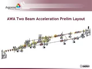
Two-beam acceleration(Parallel wakefield acceleration) 3. High Gradient Acceleration Modulator 250KV, Klystron 1.3GHz, 25MW, 8us 250AMPs Mode Locked 2. RF power generation UV Laser 1. Drive beam generation
e+ e- linear collider X-ray light source THz generation (a few) applications
1. e+ e- collider HEP • 25 MV/m, 0.5 TeV, 31 km Current Approach: superconducting RF
Argonne Approach: Flexible Linear Collider* HEP two-beam acceleration • 250 MV/m, 3 TeV, 18 km • Core of the two-beam acceleration concept: • Short rf pulse: tens of nanosecond • Modular TBA scheme: energy scalable easily *(See C. Jing’s talk)
2. Multiuser X-ray FEL User Facility BES Capable of serving ~2000 scientists/year Laser-like X-rays (like 4th generation light sources) (like 3rd generation light sources) ~100 kHz X-rays Beam Spreader ~1 MHz injector 50 MeV 2 GeV experimental end stations —Current Approach— superconducting RF $$$ Flexible x-ray beamlines (Tunable pulse length, seeded, 2 color seeded, SASE)
Argonne Approach dielectric wakefield accelerating linacs BES Collinear wakefield acceleration 750m 350m 200 MeV 2 GeV extremely low-cost alternative ~50 m experimental end stations ~50 m • Facility Footprint • 350m x 250m ~25 m ~50 m ~100 m ~30 m ~50 m • 3. Low Energy • Beam • Spreader 1. High Gradient (100 MV/m) DWFA linac 2. Room Temperature dielectric
Ultra-flexible facility dielectric wakefield accelerating linacs Collinear wakefield acceleration • Flexible accelerator beamlines • Flexible x-ray beamlines 1.2 GeV 100 pC 0.5 keV X-rays 2.4 GeV 50 pC End Stations 1 keV X-rays Configurable DWFA Accelerator Configurable FEL Array … … … …
3. THz generation: Capability gap BES 7.8GHz power extractor (40MW) 100MV/m gradient demonstration Enhanced Transformer Ratio: 3.4 Tunable DLA structure 26GHz power extractor Diamond breakdown experiment (300MV/m) Bunch Train generation at the AWA Wakefield Mapping diamond THz source at AWA Chirp correction Tunable THz GV/m Tunable 0.3-10 THz High power (155 mJ) Narrow band (1% BW) 1GHz 10GHz 30GHz 100GHz 300GHz 1THz 3THz AWA ATF BNL 15 FACET SLAC
Argonne Approach: dielectric wakefield accelerator-based AWA (10nC / 6.3mm) 0.5 GW peak, 0.3THz, 320ps pulse, 1%BW, 155mJ pulse Stage I Stage II Stage III Energy modulation via self-wakefield Chicane energy modulation conversion to bunch train THz radiation wakefield structure THz Tunable 100% source: Range: 0.3-1.5 THz Pulse bandwidth: 1% Energy in pulse: ~ mJ Measured beam spectrum Energy chirped rectangular beam Measured beam spectrum Energy modulated rectangular beam Bunch train frequency content Flexible: each step has a tuning range
Then The awa facility
Highlights of the Accelerator R & D group in the past Collinear wakefield • Invented the direct wakefield measurement technique. • First demonstration of collinear Wakefield Acceleration: • Dielectric Structures, Metallic Structures, and Plasmas • First Ever plasma wakefield acceleration in underdense regime (non-linear) (with UCLA). • First Ever 100 nC RF photocathode gun and Linac. • First Ever high power RF generation from dielectric wakefield structure accelerator. • First Ever dielectric based two beam acceleration experiment. • Discovered new multipactoring regime in dielectric structure. Drive beam generation RF generation Two-beam
The AWA facility (PAST, ca. 2008) ~ 1 meter 8 MeV 15 MeV Experimental Area soleniodlenses YAG2 Quads YAG1 Spectrometer Laser In Linac rf-gun Direction of beam propagation AWA Laser System • Single bunch operation • Q = 1-100 nC(reached 150 nC, World record?) • 15 MeV, 2-2.5 mm bunch length (rms), • emittance < 200 mm mrad (at 100 nC) • High Current: ~10 kA • Bunch train operation • 4 bunches x 20 nC (current) • 16 bunches x 5 nC (current)
RF power generation (PAST) Dielectric Power Extractors Dielectric-Loaded deceleration waveguide 7.8 GHz 40 MW TM01-TE10 coupler rf output port Downconverted signal 26 GHz 20 MW 11.44+14.576=26.016 GHz Power limited by drive beam
High Gradient Dielectric Wakefield Test (PAST) Wakefield Measurements: Q=75 nC e Cu 8.6 GHz 100 MV/m Gradient limited by drive beam
Now The awa facility
Key components of the AWA Upgrade 15 MeV beam Mg photocathode • Drive beam: 15 MeV 75 MeV • Restore two beam accelerator capability • Beamline switchyard • High quantum efficiency cathode …Before 4. Cs2Te photocathode After… 2. 15 MeV witness beam 1. 75 MeV drive beam: RF gun & six rf cavities 3. beamlineswitchyard
Capabilities of the AWA Upgraded Facility • Higher RF power generation: 40 MW ~ GW level • Higher gradients:100MV/m 0.5 GV/m in long structures • Sustained acceleration: witness DE: 1MeV ~ 100 MeV • Restore two beam accelerator capability: • Drive bunches to excite wakefields & acceleration of witness bunch. • Beamline switchyard • two-beam-acceleration • staging • collinear wakefield acceleration • phase space manipulation
The AWA Upgrade drive beam 75 MeV Direction of beam propagation drive gun Upgrade Goals Original Drive Beam (Achievements) Upgraded Drive Beam (Targets) • Single bunch operation • 75 MeV • Q = 0.1-100 nC • @ 100 nC • sz = 2 mm • High Current: ~16 kA • emittance < 200 um • Bunch train operation • 10 bunches x 100 nC • 32 bunches x 30 nC • Train Length = 10 - 50 ns • Single bunch operation • 15 MeV • Q = 0.1-100 nC • @ 100 nC • sz = 3 mm • High Current: ~11 kA • emittance < 200 um • Bunch train operation • 4 bunches x 20 nC • 16 bunches x 5 nC • Train Length = 10 - 25 ns
The AWA upgrade beamlines experimental area • RF power generation • Collinear Wakefield • TBA • Wakefield Measurement • EEX • Bunch compression 75 MeV drive beam 15 MeV witness beam 75 MeV drive beamline installed Feb 2013
PlannedRF Power Generation 26GHz power extractor Dielectric 11.7GHz metallic power extractor is under development Metallic (2pi/3 mode)
PlannedTwo Beam Acceleration Experiment 26GHz Stage I DWPE a=3.5mm; b=4.53mm; eps=6.64; L=30cm drive (75MeV) 16 bunches x 60nC/bunch, z=2mm drive (65MeV) -10MeV (loss) • RF Power Generation • 767MW x15ns • 26GHz rf 26GHz Stage II DLA a=3mm; b=5.03mm; eps=9.7; Vg=11%c; L=30cm witness (10 MeV) Q=1nC, z=1mm, e=1.5 um witness (85 MeV) +75 MeV (gain) Ez = 250MV/m
Longer Term Goal: Staging for Two Beam Acceleration Reverse the beam Option 1 Drive Beam stage I stage II Witness Beam Drive Witness Reverse the RF =2 Drive Beam 0.5m Option 2 2m Witness Beam Delay the RF Drive *Option 3: Delay the beam Witness
Plannedcollinear wakefield acceleration @ AWA drive z-direction witness z-direction Structure Parameters Beam Parameters Estimated Gradient 75MeV beam 8 bunches 40nC/per bunch σz=2mm • Beam hole=3mm • Quartz tube • Freq.=29.9GHz ~500MV/m on axis
Planneddemonstration of bunch shaping using a double-dog leg EEX beamline for high R at the AWA Facility The Argonne Wakefield Accelerator Facility Low Energy (15 MeV) beamline TDC B2 B1 RF Photocathode Gun 8 MeV 15 MeV 20 deg Quads Linac B4 B3 B2 B1 chirp multiple masks on motorized actuator x’ slope x, y beam size Key tunable parameters
Planneddemonstration of bunch shaping using a double-dog leg EEX beamline Example: Experiment I - Shaping capability Multiple masks will be used to study the bunch shaping capability of the double dog-leg EEX beamline
Drive Diagnostic Beamline To be installed Summer 2013 TEST AREA 75 MeV Longitudinal: Dp, p [MeV] A A A 0.762m 1m 0.762m End of linac DIAGX8 dump DIAGX7 1.0 m 1.0 m 0.4 m 1.5 m 1m A 15 deg Cav 6 dump DIAGX2 DIAGX3 2m 1m Def Cav DIAGX5 DIAGX4 DIAGX1 DIAGX6 Longitudinal: sz [mm] Q[nC] Transverse: ey,rms,normalized [mm] Transverse: sx,y[mm] USAF target YAG+ mirror DIAGNOSTIC CROSS Slit Trim OTR Quad BPM ICT A
AWA facility capabilities 75 MeV Drive Microbunchcharge: 100 nC Train charge: 1000 nC (10 x 100 nC, 32 x 30 nC) Ramped trains & single bunches 15 MeV Witness (1-100 nC) Applications e+ e- collider XFEL RF-THz power generation High Transformer Ratio Two-beam acceleration Collinear wakefield acceleration Next steps Drive and witness beamlines are installed, Awaiting final safety approval Drive beamlinecommisioning – Summer-Fall 2013 Generate and characterize single bunches and trains Condition 6 RF cavities Install diagnostic beamline Begin full beam commissioning at 75 MeV First wakefield experiments – Fall 2013 Wakefield measurementsystem– 2014 summary