Download
1 / 12
130 likes | 138 Vues
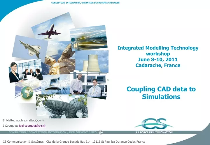
Integrated Modelling Technology workshop June 8-10, 2011 Cadarache, France. Coupling CAD data to Simulations. S. Matteo: s ophie.matteo@c-s.fr J Courquet : joel.courquet@c-s.fr CS Communication & Systèmes , Cite de la Grande Bastide Bat 914 13115 St Paul lez Durance Cedex France.

E N D
Integrated Modelling Technology workshopJune 8-10, 2011Cadarache, France Coupling CAD data to Simulations S. Matteo:sophie.matteo@c-s.fr J Courquet: joel.courquet@c-s.fr CS Communication & Systèmes, Cite de la Grande Bastide Bat 914 13115 St Paul lez Durance Cedex France
Coupling CAD data to Simulations CAD-CAE link context A CAD-CAE link process is the process allowing first of all the identification and extraction of the needed product information (geometrical mainly) from the PLM and any other geometrical information sources, then the progressive transformation into a disciplinary model, incorporating discipline knowledge and integrating discipline information in association with the geometry The upstream end of the CCL process is composed of the geometry, whatever the source information may be. The downstream end is more difficult to define since transition towards the discipline-specific model is continuous; the utmost limit is the model ready to be solved, and in the general situation, this limit depends on the most adapted tools for pre-processing (the limit lies between the last generic tools and the discipline-specific tool). Post-processing of analysis information and projection onto a geometrical reference, either for communication or for transfer to another discipline sharing interfaces on the same geometries is also part of the CCL generic process. DMU/SI Assembly Idealisation/Meshing Post processing
Coupling CAD data to Simulations Elementary Design process Global IS ETL Design Domain x DMU Apply BC Post processing Extract data DMUs Filter data Cut back (all Section but xx) Create data Define attribute (material labels, thicknesses) Key domain Functional Data Program answer Extract data From functional DB Analyze BC Definition Build model Assembly model Idealization Simulate Post processing Apply BC Mesh xD model Methods Program Design Roadmap Analyze & decomposition Experience Plan Domain y Apply BC Post processing
Coupling CAD data to Simulations CCL Functionnal architecture
Coupling CAD data to Simulations CCL offers and capabilities
Coupling CAD data to Simulations CCL end to end chain for parameterized geometry
Coupling CAD data to Simulations CCL end to end chain for parameterized geometry
Coupling CAD data to Simulations Emerging CCL breakthrough: Isogeometric analysis Isogeometric analysis introduced in 2005 by Prof. T.J.R. Hughes; University of Texas at Austin. The conversion of data from CAD into an FE mesh is a significant bottleneck in the design/analysis process. This step often exceeds the time and cost associated with the calculation of the analysis solution itself. In addition, complex association mechanisms are required to ensure the appropriate consistency between design and analysis when the design is updated. Isogeometric analysis is a technology that offers the potential to completely remove this issue. The basic elements feeding an Isogeometric solver are NURBS (Non Uniform Rational B-Splines). NURBS are used in CAD tools to define the design. The need to transform and simplify the representation, as with a standard FE process, thereby disappears completely. Such a native consistency between design geometrical information and the analysis process offers the opportunity to drastically change the way in which a detailed structural analysis is performed. • [1] Isogeometric analysis: toward unification of CAD & FEA • HUGHES Tom; Wiley 2009
Coupling CAD data to Simulations Emerging CCL breakthrough: STEP Standards • STEP (STandard for the Exchange of Product Model Data) is an international standard addressing the representation and exchange of product data. Over the last two decades, STEP has been expanded from the product design phase to incorporate later life-cycle phases, such as maintenance and repair, and extended to cover aerospace, automotive, electrical, electronic, and other industries. In its initial conception, STEP focused on information exchange in the phases of product design and machining, producing Application Protocols (AP) such as • AP203: Configuration controlled 3D designs of mechanical parts and assemblies. AP203 delivers CAD data in a neutral format that is readable by most CAD systems • AP204: Mechanical design using boundary representation. • AP214: Core data for automotive mechanical design processes, and • AP224: Mechanical product definition for process plans using machining features. • AP233 Systems engineering data representation AP233 is targeted to support the needs of the systems engineering community. It provides neutral data models as communications pipelines to exchange and integrate information between systems engineering tools. It is built from a set of reusable information model “modules” for compatibility across application domains. (http://ap233.eurostep.com )
Coupling CAD data to Simulations Emerging CCL breakthrough: STEP Standards
Coupling CAD data to Simulations Conclusion • In the time available it has been carried out a first comprehensive analysis of the CCL tools, issues, areas for improvement and scenarios for evolution. • Integrating the A/C design and validation process presents unique challenges due to highly complex and mostly conflicting disciplines such as aerodynamics, structures and manufacturing. • In this context, CCL capabilities are to be considered as a critical foundational element for design and M&S. Virtually every facet of CCL success depends on fielding of advanced technologies supporting superior capabilities of extracting relevant data from IS, agility from transforming geometrical sources, intelligence gathering, communications for MDO or multi scale purpose, tactical domain design planning • The disconnection between the CAD representation and the PDE solver as it is produces a fragmented and inefficient process. This leads to: • On the first hand, CAD vendors and companies have concentrated their effort on understanding the specific needs of different CAD packages such as CATIA, ProE and SolidWorks and means to exchange/convert this geometry information with the simulation software. CAD systems provide today parametric and feature-based modelling methods and support frequent model changes or neutral file format like STEP. • On the other hand to the development of rather generic meshing enablers such as CAPRI, ANSYS workbench enables automatic simulation workflow upon parametric geometries, which is indeed for design optimisation. • Except for geometry-based data transfers, there is neither generic exchange nor integration of data capabilities for interdisciplinary product development available. Therefore in order to ensure an efficient link between CAD and solver, CCL platform will have to provide a set of elementary services. Each domaun need will be satisfied by a dedicated effort of elementary CCL services integration.