Download
1 / 1
10 likes | 153 Vues
SQUIGGLE Nanomanipulator P13372. Guide: William Nowak , Product Engineer at Xerox Customer: Dr. Michael Schrlau at RIT ’ s NBIL Lab in conjunction with New Scale Technologies (Victor, NY). Problem. Dime as size reference.

E N D
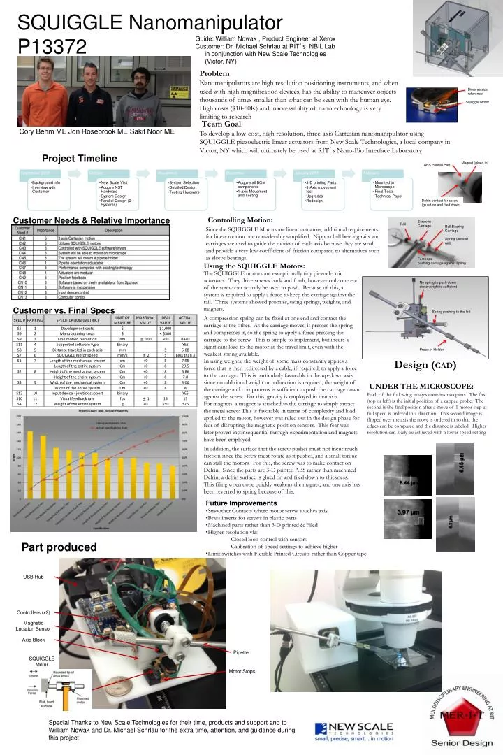
SQUIGGLE Nanomanipulator P13372 Guide: William Nowak , Product Engineer at Xerox Customer: Dr. Michael Schrlau at RIT’s NBIL Labin conjunction with New Scale Technologies (Victor, NY) Problem Dime as size reference Nanomanipulators are high resolution positioning instruments, and when used with high magnification devices, has the ability to maneuver objects thousands of times smaller than what can be seen with the human eye. High costs ($10-50K) and inaccessibility of nanotechnology is very limiting to research Squiggle Motor Cory Behm ME Jon Rosebrook ME Sakif Noor ME Team Goal To develop a low-cost, high resolution, three-axis Cartesian nanomanipulator using SQUIGGLE piezoelectric linear actuators from New Scale Technologies, a local company in Victor, NY which will ultimately be used at RIT’s Nano-Bio Interface Laboratory Project Timeline Magnet (glued in) ABS Printed Part No spring to push down since weight is sufficient Delrin contact for screw (glued on and filed down) Customer Needs & Relative Importance Controlling Motion: Spring pushing to the left Since the SQUIGGLE Motors are linear actuators, additional requirements for linear motion are considerably simplified. Nippon ball bearing rails and carriages are used to guide the motion of each axis because they are small and provide a very low coefficient of friction compared to alternatives such as sleeve bearings. Probe in Holder Using the SQUIGGLE Motors: Screw in Carriage The SQUIGGLE motors are exceptionally tiny piezoelectric actuators. They drive screws back and forth, however only one end of the screw can actually be used to push. Because of this, a system is required to apply a force to keep the carriage against the rail. Three systems showed promise, using springs, weights, and magnets. A compression spring can be fixed at one end and contact the carriage at the other. As the carriage moves, it presses the spring and compresses it, so the spring to apply a force pressing the carriage to the screw. This is simple to implement, but incurs a significant load to the motor at the travel limit, even with the weakest spring available. In using weights, the weight of some mass constantly applies a force that is then redirected by a cable, if required, to apply a force to the carriage. This is particularly favorable in the up-down axis since no additional weight or redirection is required; the weight of the carriage and components is sufficient to push the carriage down against the screw. For this, gravity is employed in that axis. For magnets, a magnet is attached to the carriage to simply attract the metal screw. This is favorable in terms of complexity and load applied to the motor, however was ruled out in the design phase for fear of disrupting the magnetic position sensors. This fear was later proven inconsequential through experimentation and magnets have been employed. In addition, the surface that the screw pushes must not incur much friction since the screw must rotate as it pushes, and a small torque can stall the motors. For this, the screw was to make contact on Delrin. Since the parts are 3-D printed ABS rather than machined Delrin, a delrin surface is glued on and filed down to thickness. This filing when done quickly weakens the magnet, and one axis has been reverted to spring because of this. Rail Ball Bearing Carriage Spring (around rail) Forecepspushing carriage against spring Customer vs. Final Specs Design (CAD) Gravity Return Force Design (CAD) UNDER THE MICROSCOPE: Each of the following images contains two parts. The first (top or left) is the initial position of a capped probe. The second is the final position after a move of 1 motor step at full speed is ordered in a direction. This second image is flipped over the axis the move is ordered in so that the edges can be compared and the distance is labeled. Higher resolution can likely be achieved with a lower speed setting. The entire blocks on the carriage were to be machined from Delrin, however due to time constraints these were 3-D Printed from ABS. A thin layer of Delrin was glued to the ABS to compensate and filed down even thinner to allow for attraction of the magnets through it. Particularly vigorous filing with a metal file was shown to demagnetize the magnet, and one axis was then returned to using the spring. • Future Improvements • Smoother Contacts where motor screw touches axis • Brass inserts for screws in plastic parts • Machined parts rather than 3-D printed & Filed • Higher resolution via: Closed loop control with sensors Calibration of speed settings to achieve higher • Limit switches with Flexible Printed Circuits rather than Copper tape Part produced USB Hub Controllers (x2) Final PIC GOES HERE WITH housing Magnetic Location Sensor Axis Block Pipette SQUIGGLE Motor Motor Stops Special Thanks to New Scale Technologies for their time, products and support and to William Nowak and Dr. Michael Schrlau for the extra time, attention, and guidance during this project


![READ [PDF] The Squiggle](https://cdn7.slideserve.com/12439841/slide1-dt.jpg)
![[PDF READ ONLINE] The Squiggle](https://cdn7.slideserve.com/12526070/slide1-dt.jpg)
