Download
1 / 45
450 likes | 672 Vues
Evaluation of Radiation Hardness in the Electronics for the LHC Upgrade. August 4 th , 2011 Irene Zawisza. Outline. Particle physics Introduction to collider experiments Large Hadron Collider (LHC) Compact Muon Solenoid (CMS) Super LHC (SLHC) upgrades

E N D
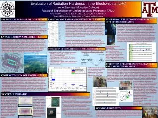
Evaluation of Radiation Hardness in the Electronics for the LHC Upgrade August 4th, 2011 Irene Zawisza
Outline • Particle physics • Introduction to collider experiments • Large Hadron Collider (LHC) • Compact Muon Solenoid (CMS) • Super LHC (SLHC) upgrades • Study of radiation tolerance of electronics for CMS Endcap Muon system upgrade • Radiation effects • Estimates and measurements of neutron rates • Testing of upgrade electronics • Accumulated effects: soft neutron exposure • Single event upsets (SEU): hard neutron exposure
The Standard Model of Particle Physics • SM is used to describe how particles behave on the subatomic level. • Describes the universe through fundamental particles and their interactions • Four forces • Several fundamental particles • Each mass-particle also has an anti-particle • Describes over 200 “composite” particles • Requires the Higgs Boson
Limitations of The Standard Model • SM is not complete, e.g. • The model predicts existence of not yet observed Higgs boson particle • Predicted by SM, the Higgs boson, is expected to give particle masses through their interactions with the Higgs • It cannot explain dark matter • Astrophysics experiments show that the universe has five times more of dark matter then of visible matter • Cannot explain matter/anti-matter asymmetry • Gravity is not covered by SM, and there is no easy way to incorporate it
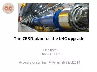
Large Hadron Collider (LHC) • To understand the development of the Universe, we reproduce conditions experienced shortly after the Big Bang • We build these large machines so we can • produce new, interesting particles • rare processes occur • study decays of particles (measure lifetimes and various asymmetries) • find what governs the underlying physics • World’s largest particle accelerator • We need a lot of energy, because most interesting particles are heavy • 14 TeV proton-proton (pp) collisions • 17 miles circumference • Crosses between Geneva, Switzerland and Cessy, France
How Do We See These Things at LHC? • Observe production of new, never-seen-before particles in high energy collisions. • Higgs Boson, dark matter particle, …? • How is this done? • Collision events have particles which decay to other lighter, stable particles which are detectable. • Use detected particles to reconstruct what occurred in a collision • E.g, momentum and energy of particles. • The detection is performed by a complex detector system
CMS Detector Slice • Superconducting Solenoid – strong magnet, 4 Tesla • Magnetic field bends trajectories of charged particles • Muons are a special particle that are easy to detect.
Compact Muon Solenoid (CMS) Detector • One of two general purpose detectors at the LHC. • The detector reads out using electronics. High-speed “triggers” that utilize fast electronics are used for event selection.
CMS Muon Endcap • The muon endcap is separated in four muon endcap stations, which are built from Cathode Strip Chambers (CSC) • 468 CSC that detect muons • Each CSC has six layers of cathode strips separated by gas gaps and anode wires • Detected signals are read out by complex electronics system
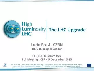
Upgrade of LHC and CMS • LHC beam intensity will soon be increased • More collisions in a period of time. • Larger chance to observe rare processes • Upgraded LHC will have luminosity that is x10 higher then it was initially designed • The expected average of 25 pp interactions per bunch crossing at design luminosity would increase to 250 • The many components of the CMS detector system must also be upgraded to handle higher rates • Higher luminosity means higher radiation levels that the detector electronics should be able to handle Collision reconstruction at current LHC intensity Collision reconstruction at upgraded LHC intensity
Radiation Effects on Electronics • Neutrons are the main radiation source in the CMS cavern • Radiation damage is dependent on the neutron energy • high (“hard”) and low (“soft”) energy neutrons • Types of radiation damage to electronics: • Single Event Upset (SEU) • Digital upsets caused by hard neutrons • These effects are transient • Displacement or distortions • Silicon crystal defects caused by hard and soft neutrons • This is permanent and accumulates over time
Relationship of Simulation and Real Data Measurements of Neutron Rates in the CMS Detector FLUKA simulation (neutrons flux) GEANT4 simulation • There are various simulation packages and parameterizations for neutron studies (e.g., FLUKA, GEANT) • The estimates for electronics radiation exposure are based on the neutron flux estimates from FLUKA • To check FLUKA predictions, we need to compare them to the recent experimental data measurements and simulation results from GEANT4 Electronics radiation exposure CSC Hit Rate CSCHit Rate compare Data
Comparing Simulations and Data Measurements • For the most part, the data agrees with the simulation results within acceptable range • Simulation gives a reasonable representation of the actual exposure rates in the CMS cavern
Trigger Mother Board Upgrade • Having established that the simulation is trustworthy, we design prototype electronics and test for their dependability. • TMB electronic component requirements: • Operational Stability – the boards are evaluated to guarantee consistency before irradiation and to determine satisfactory performance after radiation • Temperature Regulation – verify the steady state temperature is within a safe operating range • Radiation Tolerance – determine which electronic circuits survive SLHC radiation exposure • Our experimental studies will establish which electronic components are suitable for the LHC upgrade FPGA Design Current FPGA: Virtex 2 Upgrade FPGA: Virtex 6 – two times faster with five times more logic capability
Radiation Tolerance Experiments • Determining how sensitive electronic components are to radiation levels • Radiation tolerance testing is a two-fold process: • Soft Neutron Exposure – low energy reactor neutrons • Only tests for displacement damage • Hard Neutron Exposure – requires a particle beam • Only required for digital circuits • Neutron beams are difficult • High energy proton beam in the K500 TAMU Cyclotron used to mimic hard neutron exposure. • Above 20 MeV, proton and neutron radiation damage is equivalent. • Due to the proton charge, the beam can be focused using magnets. • The proton beam tests for displacement damage and digital upsets.
Soft Neutron Exposure – Low Energy Radiation • Soft neutron exposure done at the Nuclear Science Center (NSC) nuclear reactor. • The first exposure of neutrons was the equivalent to the total radiation seen by CMS over ten years after the upgrade • The second exposure is the equivalent of an additional twenty years worth of radiation seen by CMS. • Analysis of electrical circuits performance • Analysis determines if they operate reliably with expected voltages after the radiation exposure
Voltage Regulator TestsVoltage Operation Testing • Four different test boards containing all potential upgrade components • 20 unique circuits • 10 different voltage regulators • These circuits most provide consistent power for the FPGA • Many tests have been done to check operating stability prior to radiation • The boards were powered and were tested about 10 times per day • All pre-radiation trials proved to be stable over several days of testing.
Radiation Tolerance – Voltage Regulator Tests • VR2 – voltage remains constant both before and after radiation • VR7 – voltage drops, seeing no improvement, the chip has serious degradation after radiation • VR10 – voltage drops, but voltage recovers somewhat over time
Voltage Regulator TestsThermal Testing • Flir Extech i5 Thermal Imager • Thermal images were taken prior to each voltage measurements • Different conditions were tested to simulate realistic conditions in LHC electronics • Natural air flow versus cooling – initial testing showed that a fan was useful in quickly cooling the boards • Heat sinks – initial testing showed that heat sinks made little difference
Thermal Testing – Temperatures of Operating Voltage Regulators VR9 – B2 VR9 – B1 VR7 – A2 VR7 – A1 VR2 – B2 VR2 – B1 Voltage Regulator
Conclusions on Voltage Regulator Tests with Soft Neutrons • Different voltage regulators offered different results, but we wanted to know the survivability based on pre and post irradiation • Some circuits do not survive SLHC radiation levels • Interesting data suggests that some circuits might recover with time • On board A1 circuits – 9, 10 • On board A2 circuit – 9 • Additional tests after two weeks showed no additional change • The final TMB design should focus on circuits which do not fail and show very little signs of degradation • We found a variety of circuits that work for the robust operation of CMS.
Hard Neutron Exposure – High Energy Radiation • In our study, the K500 Cyclotron provided an ionized hydrogen (proton) beam at 55 MeV energy • Expose each TMB component for approximately 90 minutes. • Simple tests performed on the TMB determine the rates of digital upsets (SEU).
Conclusions for TMB Board Testing • Based on preliminary observations of Cyclotron proton tests, after the beam upgrade at LHC we made the following preliminary observations about the new electronics: • We will probably see about 3 errors every day on each fiber optic link to the TMB board. • There might be a logic error in a TMB FPGA about every 5 minutes • The FPGA configuration PROM is not susceptible to logic upsets • The level-shifting translator chips never have any logic upsets • However, these are very preliminary estimates with large uncertainty at this time. 1-Snap RX 2-Snap TX 3-FPGA 4- Finisar
Summary • Our motivation is to find undiscovered, new particles by using large accelerators and detectors to gain a better understanding of the development of the Universe. • The detectors requires fast electronics that operate under the harsh conditions of the CMS detector. • We found suitable voltage regulators and TMB electronic components, which will enable the robust operation of CMS after the SLHC upgrade.
Acknowledgements • Special thanks to: • Dr. Alexei Safonov, Dr. Jason Gilmore, Dr. VadimKhotlilovich, Indara Suarez, and Jeffrey Roe for all your help and guidance • Dr. Sherry Yennello, Larry May, and the rest of the Cyclotron Institute
How Does the Higgs Boson Give Particles Mass? • According to the Standard Model, the proposed Higgs mechanism • as particles collide with the Higgs boson, they acquire mass. • Photons do not interact with the Higgs, and are therefore massless. • All particles supposedly change handedness when they interact with the Higgs. E.g. Left-handed particles become right-handed. • Neutrinos: Experiments show that neutrinos are always left-handed, and right-handed neutrinos are non-existent in the Standard Model. Theory predicts that neutrinos can never acquire mass, because they are never going to change handedness. However, in one extension of the Standard Model, both right and left handed neutrinos can occur. These are known as Dirac neutrinos, and are able to interact and acquire mass through the Higgs mechanism. Right-handed neutrinos are much more weakly interacting than other particles
There are many stages to the LHC collider • Starts off in linear accelerators • Travels through the proton synchrotron • Goes to the super proton synchrotron, where particles are accelerated to speeds that are the lowest threshold for the LHC accelerator • Strong magnets keep the beam maintained in a circular path Super Proton Synchrotron Proton Synchrotron Linear Accelerator Linear Accelerator
Data Measurements of Neutron-Induced Hit Rates From Chad Jarvis, UCLA • Need to know neutron rates to predict electronics radiation damage • Neutron rates at CMS are not known well experimentally • Special configuration of the detector was used to measure the neutron-induced hit rate • Since neutrons have long lifetimes, we measure the neutron-induced hit rate indirectly by using the rate of detector signals that occur at times that are not close to the times of collisions • Gives us a chance to check the neutron simulation tools • To compare these results to various simulation results, simulation results should be brought to the same luminosity and center of mass energy CSC hit flux numbers in the plot are for luminosity L=1.9*1032 1/(cm2s)
Available simulation Predictions • Simulation calculation is the flux of neutron-induced hits per layer of CSC • We have three simulation predictions: Using FLUKA, we obtain: • CMS Technical Design Report (2000) – TDR Using GEANT4 package, we obtain full CMS detector simulations with two options for special parameterizations (“physics tables”) for neutron studies: • QGSP_BERT_HP – older, better tested parameterization • QGSP_BERT_EMLSN – newer, faster, with more recent neutron interactions data, but far less tested
Analysis of TDR Simulation • The results from TDR were available to us as plots of neutron-induced hit fluxes per layer of CSC • Represented as black circles • Estimated at design LHC luminosity, 1034 1/(cm2s), and beams center of mass energy of 14 TeV • What we did with it: • Extracted approximate numeric values and uncertainties from the plots • Scaled the numbers to appropriate luminosity and energy • Calculated averages for each chamber type
CMS: End Cap Region • As we saw before, the protons collide in the “center” of the detector. From here, the particles go into the tracker. • Made of cathode strips and anode wires • When a charged particle penetrates the chamber, • the gas ionizes • electron avalanche • charge collected on anode wire • image charge collected on cathode strip
Hierarchy of CSC Trigger Electronics Our studies focus on the trigger electronics of the CMS Muon Endcap. Cathode Strip Chambers (CSC) Cathode Strips Anode Wires Anode Front End Board (AFEB) Cathode Front End Board (CFEB) Cathode Local Charged Tracks (CLCTs) Anode Local Charged Tracks (ALCTs) TMB AFEB Trigger Mother Board (TMB) Muon Port Card (MPC) CSC Track Finder (CSCTF) Global Muon Trigger
Anode and Cathode Front End Boards – AFEB and CFEB • CFEB • 16 channel amplifier-shaper ASIC • Amplifies signals and shapes into semi-Gaussian voltage pulses • Comparator ASIC • Locates charge clusters center on strips to a half strip accuracy • Marks the time of the pulse • Signals received in the anode wires and cathode strips are sent to the anode/cathode Front End Board (AFEB/CFEB) • AFEB • 16 channel amplifier-shaper-discriminator ASIC • Amplifies signals • Picks signals that are in a preset threshold with precise time accuracy Cathode Front End Board Anode Front End Board
Anode and Cathode Local Charged Tracks – ALCT and CLCT • Finds hit patterns that occur in the cathode strips and anode wires that trace the signature to the collision vertex • ALCT • Looks at the six layers to see exactly where hits occurred in that section • Makes 2D designs of hit patterns and tries to find any possible muons • Timing is key • Low Coincidence timing – establishes the timing of hits • High Coincidence timing – used to establish the possibility that a hit is actually a muon signature • CLCT • Located on the Trigger Mother Board (TMB) • Makes 2D LCTs • Timing is key • Coincidence of hits in the six layers must be consistent with high momentum muon tracks
Trigger Mother Board – TMB • The anode and cathode tracks that were made into 2D images are combined into 3D projections here • Timing Coincidence • The 3D projections are given vector values • While looking for muons, if multiple matches of tracks are found, TMB picks the best two • Looks at how many layers were hit in the ALCT and CLCT stage • Gives vector values to the LCTs • Sends any generate 3D LCT to the Muon Port Card (MPC)
Muon Port Card – MPC • Responsible for receiving LCTs from • One 60º section of a station from ME2-ME4 • 3 from inner 20º chambers • 6 from outer 10º chambers • One 20º section of an ME1 station • 2 from 10º chamber • Selects 3 best LCTs and sends them to the Cathode Strip Chamber Track Finder (CSCTF) through optical fiber connections
Cathode Strip Chamber Track Finder – CSCTF • Takes two LCTs of different stations and combines them • Occurs for hits that appear to be muons only • Combined data is from the collision origin to the hit track • Assigns a transverse momentum value to muon matches • The larger a scattering angle, the higher the momentum and energy will be • Muon tracks are sent to the Muon-Sorter • Takes the four best tracks in entire CSC system and sends them to the Global Muon Trigger (GMT)
Global Muon Trigger – GMT • Receives the four best Drift Tube (from the Barrel region of CMS) and four best CSC muon candidates • Combines, based on proximity in space (η, φ), all data and ranks the candidates • Rank is based on • detector type • transverse momentum value (pt) • quality • pseudorapidity (η) • The four best candidates are sent to the Global Trigger
Before-After Summary: Boards A1 & A2 • Circuits in RED have signs of performance degradation • These have further analysis on following slides • Circuits highlighted in Yellow improved significantly over time
Before-After Summary: Boards B1 & B2 • Circuits in RED have signs of performance degradation • These have further analysis on following slides
TMB Board Test • The FPGA Board is able to run simple tests • Send data in bunches • First half of a byte is the end of the previous byte • Random number generator • A loop back board • Compare the numbers that are generated initially to the numbers that have traced the system • If the numbers are the same, then test passes, otherwise, the test fails • A reset button is required that is long enough to run the cavern of the cyclotron