Download
1 / 36
360 likes | 550 Vues
Recent p rogress of J-PARC RCS beam commissioning. Workshop on Booster Performance and Enhancements Nov . 23-24, 2015, Fermilab Michikazu Kinsho (J-PARC Center, JAEA). Contents Outline of the J-PARC RCS RCS operational history 1-MW beam tests

E N D
Recent progress of J-PARC RCS beam commissioning Workshop on Booster Performance and Enhancements Nov. 23-24, 2015, Fermilab Michikazu Kinsho (J-PARC Center, JAEA) • Contents • Outline of the J-PARC RCS • RCS operational history • 1-MW beam tests • Recent effort for further beam loss mitigation • Summary
J-PARC (JAEA & KEK) 400 MeV H-Linac 3 GeV Rapid Cycling Synchrotron (RCS) Neutrino Beam Line to Kamioka(NU) 50 GeV Main Ring Synchrotron (MR) [30 GeV at present] Materials & Life Science Facility (MLF) JFY 2006 / 2007 JFY 2008 Hadron Experimental Hall (HD) JFY 2009
Outline of the J-PARC RCS ⇒ 400 MeV in 2013 3GeV proton ⇒ 8.3e13 in 2014 ⇒ 1 MW MLF : Material and Life Science Experimental Facility MR : 50-GeV Main Ring Synchrotron 400 MeV H- • Recently the hardware improvement of the injector linachas been completed. • The RCS have just got all the design hardware parameters • to try the 1-MW design beam operation.
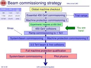
History of the RCS beam operation Injection energy upgrade Injection beam currentupgrade Einj=400 MeV Imax=30 mA Einj=400 MeV Imax=50 mA Einj=181 MeV Imax=30 mA Einj=181 MeV Imax=30 mA 1-MW-eq beam test Startup of the user program in December 2008 ~550-kW-eq beam test ~540-kW beam test Output power to MLF (kW) 500 kW for users • The output beam power from the RCS has been steadily increasing • following progressions in beam tuning and hardware improvements. • Present output beam power for the routine user program :500 kW • 1-MW beam tests from October 2014 • after completing the injector linac upgrades Main topic of this talk : - 1-MW beam experimental results - Approaches to beam loss issues
1-MW beam tests conducted after the injector linac upgrade • The injection energy was upgraded • by adding an ACS linac section in 2013 • Injection beam condition • Injection energy : 400 MeV • Peak current : 45.0 mA • at the entrance of RCS • Pulse length : 0.5 ms • Chopper beam-on duty factor : 60% • Beam intensity : 8.4 x 10¹³ppp, • correspondingto 1010 kWat 3 GeV • Operating point: • (6.45, 6.42)~(6.45, 6.38) • allow a space-charge tune shift • to avoid serious multipole resonances • Injection painting parameter: • 100p transverse painting • (“correlated painting”) • + full longitudinal painting • The injection beam current was upgraded by replacing the front-end system • (IS & RFQ) of the linac in 2014.
Transverse injection painting • Horizontal painting • by a horizontal closed orbit • variationduring injection • Vertical painting • by a vertical injection • angle change during injection Correlated painting etp= 100 p mm mrad The injection beam is painted from the middle to the outside on both horizontal and vertical planes.
Transverse injection painting Numerical simulations Transverse beam distribution just after beam injection calculated without and with transverse painting No painting Horizontal Vertical x‘ (mrad) y‘ (mrad) y (mm) Density (Arb.) x (mm) Position (mm) y (mm) x (mm) Density (Arb.) x‘ (mrad) y‘ (mrad) y (mm) x (mm) Position (mm) y (mm) x (mm) 100ptransverse painting from H. Hotchi et. al., PRST-AB 15, 040402 (2011).
Longitudinal injection painting Momentum offset injection RF voltage pattern Fundamental rf V1 RF voltage (kV) V2 Second harmonic rf Time (ms) Dp/p=0, -0.1 and -0.2% V2/V1=80% The second harmonic rf fills the role in shaping flatter and wider rf bucket potential, leading to better longitudinal motion to make a flatter bunch distribution. Uniform bunch distribution is formed Through emittance dilution by the large synchrotron motion excited by momentum offset. F. Tamura et al, PRST-AB 12, 041001 (2009). M. Yamamoto et al, NIM., Sect. A 621, 15 (2010).
Longitudinal injection painting Additional control in longitudinal painting ; phase sweep of V2 during injection Vrf=V1sinf-V2sin{2(f-fs)+f2} V2/V1=0 V2/V1=80% (A) f2=-100 deg f2=-100⇒0 deg (B) f2=-50 deg (C) f2=0 RF potential well (Arb.) The second harmonic phase sweep method enables further bunch distribution control through a dynamical change of the rf bucket potential during injection. f (Degrees)
Longitudinal injection painting Longitudinal beam distribution just after beam injection (at 0.5 ms) V2/V1=80% f2=-100 to 0 deg Dp/p=-0.1% V2/V1=80% f2=-100 to 0 deg Dp/p= 0.0% No longitudinal painting V2/V1=80% f2=-100 to 0 deg Dp/p=-0.2% Dp/p (%) Dp/p (%) Dp/p (%) Dp/p (%) f (degrees) f (degrees) f (degrees) f (degrees) Bf>0.40 Bf ~0.15 Density (Arb.) Density (Arb.) Density (Arb.) Density (Arb.) f (degrees) f (degrees) f (degrees) f (degrees) Measurements (WCM) Numerical simulations from H. Hotchi et. al., PRST-AB 15, 040402 (2011).
Painting parameter dependence of beam survival rate ● Einj=181 MeV, 539 kW-eq. intensity (Run#44, Nov., 2012) ● Einj=400 MeV, 553 kW-eq. intensity (Run#54, Apr., 2014) By adding 100p transverse painting By longitudinal painting Beam survival rate Further space-charge mitigation by the injection energy upgrade b2g3400MeV/b2g3181MeV=2.9 No painting Painting parameter ID This experimental data clearly show the big gain from the injection energy upgrade as well as the excellent ability of injection painting for the space-charge mitigation.
Painting parameter dependence of beam survival rate ●Einj=400 MeV, 553 kW-eq. intensity (Run#54, Apr., 2014) By adding 100p transverse painting By longitudinal painting Beam survival rate No painting Painting parameter ID The parameter dependence for nearly flat, but it has a similar dependence to that for the blue circles (injection energy : 181MeV).
Result of the 1-MW trial in Jan. 2015 Circulating beam intensity over the 20 ms from injection to extraction measured by CT Experimental condition 8.41 x 10¹³ ppp : 1010 kW-eq. • Injection beam condition • Injection energy : 400 MeV • Peak current : 45.0 mA • @ the entrance of RCS • Pulse length : 0.5 ms • Chopper beam-on duty factor : 60% • 8.41 x 10¹³particles/pulse, • corresponding to 1010 kWat 3 GeV • Operating point; • (6.45, 6.42) • Injection painting parameter; • ID8 (100p transverse painting • + full longitudinal painting) 7.86 x 10¹³ ppp : 944 kW-eq. 6.87 x 10¹³ ppp : 825 kW-eq. 5.80 x 10¹³ ppp : 696 kW-eq. Particles /pulse (x 1013) 4.73 x 10¹³ ppp : 568 kW-eq. • In January 10, 2015 • we successfully achieved • the 1-MW beam acceleration. Injection Extraction Time (ms) There is no terrible beam loss, but some unnecessary beam losses was detected at the arc sections.
Beam loss in the high dispersion area (arc sections) ― 8.41 x 10¹³ ppp : 1010 kW-eq. ― 7.86 x 10¹³ ppp : 944 kW-eq. ― 6.87 x 10¹³ ppp : 825 kW-eq. BLM signal (arb.) ― 5.80 x 10¹³ ppp : 696 kW-eq. ― 4.73 x 10¹³ ppp : 568 kW-eq. Extraction Time (ms) Injection • The beam losses observed for the 944-kW (blue) and 1010 kW (red) beams can be interpreted • as longitudinal beam loss arising from a distortion of the RF bucket • caused by the beam loading effect. • Such beam particles suffer from large momentum excursion and most of them are lost in • the high dispersion area, not at the collimator section located in the dispersion-free section. • This type of longitudinal beam loss has to be cured by beam loading compensation. • But then the anode power supply in the RF system had no enough margin to complete • sufficient beam loading compensation for the 1-MW beam. We carried out the anode power supply upgrade using the 2015 summer maintenance period. 1MW beam test again in October 2015
Result of the 1-MW trial in Oct. 2015 BLM signals at the high dispersion area (arc sections) Injection Extraction Run#60 ― 8.41 x 10¹³ ppp : 1010 kW-eq. ― 7.86 x 10¹³ ppp : 944 kW-eq. ― 6.87 x 10¹³ ppp : 825 kW-eq. BLM signal (arb.) ― 5.80 x 10¹³ ppp : 696 kW-eq. ― 4.73 x 10¹³ ppp : 568 kW-eq. Run#64 ―8.45 x 10¹³ ppp : 1014 kW-eq. ―7.25 x 10¹³ppp :870 kW-eq. ―6.09 x 10¹³ppp : 731 kW-eq. ―5.05 x 10¹³ppp : 606 kW-eq. ―3.94 x 10¹³ppp : 473 kW-eq. BLM signal (arb.) Time (ms) Longitudinal beam loss was well mitigated as expected by sufficient beam loading compensation after the RF power supply upgrade.
Beam loss at the collimator BLM signals at the collimator section (dispersion-free straight section) BLM HV=-600 V ―8.45 x 10¹³ ppp : 1014 kW-eq. ―7.25 x 10¹³ppp :870 kW-eq. ―6.09 x 10¹³ppp : 731 kW-eq. ―5.05 x 10¹³ppp : 606 kW-eq. ―3.94 x 10¹³ppp : 473 kW-eq. BLM signal (arb.) Time (ms) Injection Injection bump “ON” BLM signal (arb.) Foil scattering beam loss during charge-exchange injection< 0.1% Time (ms) • The beam loss at the collimator section mainly arises from foil scattering during injection. • The other beam loss, such as space-charge induced beam loss, was well minimized • by injection painting even for the 1-MW beam. • The remaining beam loss for the 1-MW beam was estimated • to be < 0.1% (< 133 W in power) << Collimator limit of 4 kW. • RCS beam commissioning made big progresses in this beam test.
Recent efforts for further beam loss mitigation The beam loss other than foil scattering beam loss was well minimized. Next subject : further mitigation of the foil scattering beam loss • Most of the foil scattering beam loss is well localized at the collimators, • but some of them with large scattering angles cause uncontrolled beam loss, • making relatively high machine activations near the charge-exchange foil; • ~15 mSv/h on the chamber surfaceafterthe 400-kWbeam operation. • ~40 mSv/h if the output beam power is increased to 1 MW as is. • This radiation level is still considered to be within the acceptable level • if assuming enough cooling time, • butit has to be reduced as low as possible in terms of preserving a better hands-on-maintenance environment. further mitigation of the foil scattering beam loss • The amount of the foil scattering beam loss • in proportion to the foil hitting rate during charge-exchange injection. One possible solution to reduce the foil hitting rate : to expand the transverse painting area.
Transverse injection painting Foil • Horizontal painting • by a horizontal closed orbit variationduring injection The foil hitting rate decreases as the horizontal painting area becomes wider, because the circulating beam more rapidly escapes from the foil thanks to the larger horizontal closed orbit variation. • Vertical painting • by a vertical injection angle change during injection Vertical painting also acts to reduce the foil hitting rate through the wider painting area than the vertical dimension of the foil. Foil Estimation of foil-hits number • The foil scattering beam loss can be reduced by larger transverse painting. • But such a large transverse painting had not been realized until recently • due to beta function beating • caused by the edge focus of the injection • bump magnets. vertical dimension of the foil : 20mm
Beta function beating caused by the injection bump magnets Horizontal (Bump off) Horizontal (Bump on) Vertical(Bump off) Vertical (Bump on) 1st super-period Beam injection is performed with a time dependent horizontal local bump orbit by using 8 sets of rectangular pulse dipoles magnets (SB1-4 & PBH1-4 ). 2nd super-period • Edge focuses are generated • at the entrance and exit of the injection • bump magnets. Beta functions (m) • There is no beta function beating on the horizontal plane, • because the horizontal edge focus effects • are canceled out by another focusing • property intrinsic on the bending plane. 3rd super-period Beta function beating caused by the edge focus of the injection bump magnets s (m)
Beta function beating caused by the injection bump magnets 1st super-period Horizontal (Bump off) Horizontal (Bump on) Vertical(Bump off) • The vertical edge focus affect the beam as is, • making 30% beta function • beating on the vertical plane • during injection period. Vertical (Bump on) 2nd super-period Beta functions (m) • The beta function beating makes a distortion of the lattice super-periodicity • and additionally excites various • random betatron resonances. 3rd super-period • Such random resonances cause an additional shrinkage of the dynamic aperture during injection period, • and leads to extra beam loss • when applying large transverse • painting. s (m) Beta function beating caused by the edge focus of the injection bump magnets
Random betatron resonances excited through a distortion of the super-periodicity Present operating point (6.45,6.42) nx+2ny=19 Vertical tune ny Vertical tune ny Horizontal tune nx Horizontal tune nx Systematic resonances Random resonances that can be additionally excited through a distortion of the super-periodicity on the vertical plane caused by the edge focus. • These random resonances cause a shrinkage of the dynamic aperture • during the injection period, and leads to extra beam loss • when applying large transverse painting. • Especially, this 3rd order sum resonance strongly affects the beam • in the present operational condition.
Correction of beta function beating • We have recently installed6 sets of pulse type quadrupole correctors (QDTs), • to compensate beta function beating, and to minimize the effect of the random resonances • through the recovery of the super-periodic condition. Vertical beta function beating was successfully corrected by QDTs, while keeping the super- periodic condition on the horizontal plane. QDT Beta function beating correction by these quadrupole correctors Before correction After correction 1st super-period 2nd super-period Beta functions (m) Beta functions (m) 3rd super-period s (m) s (m)
Beam loss reduction by QDTs BLM signals @ collimator Experimental condition • Injection beam condition • Injection energy : 400 MeV • Peak current : 29.8 mA • @ the entrance of RCS • Pulse length : 0.5 ms • Chopper beam-on duty factor : 60% • ⇒ 5.58 x 10¹³ particles/pulse, • corresponding to 670 kWat 3 GeV • Operating point; • (6.45, 6.42) Transverse painting area: 100p mm mrad (Horizontal) 100p mm mrad (Vertical) 150p mm mrad (Horizontal) 100p mm mrad (Vertical) BLM signal (arb.) • When expanding the horizontal • painting area to 150p mm mrad, • significant extra beam loss appeared. • But this beam loss was well mitigated • as expected by introducing QDTs. 150p mm mrad (Horizontal) 100p mm mrad (Vertical) • Now we are conducting the 500-kWroutine • user operation with this large transverse • painting using QDTs. • By this large transverse painting, and also by optimizing the foil position, • the residual radiation level near the charge exchange foil was well reduced as expected. + QDTs Time (ms)
1-MW beam experimental results BLM signals at the collimator section (a) 200p-mm-mrad correlated painting ~1.9% loss By the mitigation of the emittance growth caused by the nx-ny /2nx-2ny=0 resonance (b) 200p–mm-mrad anti-correlated painting ~0.8% loss By the mitigation of the nx+2ny=19 resonance BLM signals (arb.) (c) 200p-mm-mrad anti-correlated painting No chromatic corr. ~0.4% loss By the further mitigation of nx+2ny=19 resonance through the recovery of the lattice super-periodicity (d) 200p anti-correlated painting No chromatic corr. With QDTs The remaining extra beam loss is expected to be minimized by optimizing the field patterns of QDTs, and also by fine adjustment of the betatron tunes. ~0.2% loss Time (ms) We got good prospects of realizing the wide-ranging transverse painting for the 1-MW beam by introducing both QDTs and anti-correlated painting.
Averaged number of foil-hits per particle during injection ID1:etp=100pmm mrad, W=30 mm, Dx=13 mm ID2:etp=100p mm mrad, W=20 mm, Dx=9 mm ID3: etp=150pmm mrad, W=20 mm, Dx=9 mm ID4: etp=200pmm mrad, W=20 mm, Dx=9 mm 41 Number of foil hits 21 Charge-exchange foil (330-mg/cm2-thick HBC) Injection beam 12 Dx=13mm W=30 mm The foil was pulled out by 4 mm and its size is also reduced. 7 Dx=9mm W=20 mm Parameter ID • Now we perform 500-kW routine beam operation with ID3. • The present residual radiation level near the charge exchange foil is • ~4.5 mSv/h on the chamber surface, which is sufficiently within the acceptable level. • When we realize 200p-mm-mrad transverse painting, • the radiation level canbe kept at the same level as the present value • ( ~5.3 mSv/h on the chamber surface) even for the 1-MWoperation. • We continue the beam test aiming to realize the wide-ranging transverse painting before startup of the 1-MW routine user operation.
Summary • We started 1-MW beam tuning from October 2014, • and successfully achieved 1-MW beam acceleration in January 2015. • Major part of beam loss, such as space-charge induced beam • was well minimized by the injection painting technique. • The remaining beam loss is mainly from foil scattering during injection. • The transverse painting area was successfully expanded by correcting beta function beating during injection caused by the edge focus of the injection bump magnets, by which the foil scattering beam loss was further reduced. • By these efforts, now the beam loss is at the permissible level for the 1-MW routine beam operation. • The 1-MW routine beam operation is ready. • Present output beam power for the routine user program is 500kW, and we plan to continue this situation from end of this December required from the MLF. • We will be gradually increasing the routine output beam power by 100-kW step every one month or two month from next June. • If this beam power ramp-up scenario is going well, the 1-MW routine beam operation will be to start up from next autumn.
Beam loss reduction by QDTs (Run#63) BLM signals at the collimator section Experimental condition • Date : June, 2015 (Run#63) • Injection beam condition • Injection energy : 400 MeV • Peak current : 37.6 mA • @ the entrance of RCS • Pulse length : 0.5 ms • Chopper beam-on duty factor : 60% • ⇒ 7.06 x 10¹³ particles/pulse, • corresponding to 847 kWat 3 GeV • Operating point; • (6.45, 6.38) (i) BLM HV=-300 V (ii) (iii) (ii) When expanding the transverse painting area to 150p mm mrad, significant extra beam loss appeared. (iii) The extra beam loss was well mitigated as expected by introducing QDTs.
Measurement vs Numerical simulation • Measurement • (BLM signals at the collimator section) • Numerical simulation by “Simpsons” (i) (i) (ii) (ii) (iii) (iii) • The experimental results were well reproduced by numerical simulations. • We investigated more detailed beam loss mechanism • using the numerical simulation results.
Beam halo formation caused by the edge focus Transverse phase space coordinates at the end of injection calculated with etp=150p mm mrad Without edge focus • The edge focus enhances • beam halo formation • especially on the vertical plane. • The beam halo formation • causes the extra beam loss • observed when expanding • the transverse painting area. • The beam halo is well mitigated • by QDTs, by which the extra beam • loss is minimized. With edge focus With edge focus & QDTs
Random betatron resonances excited through a distortion of the super-periodicity Operating bare tunes : (6.45, 6.38) Systematic resonances Random resonances that can be additionally excited through a distortion of the super-periodicity caused by the edge focus of the injection bump magnets Vertical tune ny Horizontal tune nx • The edge focus of the injection bump magnets make a distortion • of the lattice super-periodicity only on the vertical plane. • Therefore, it selectively excites random resonances related • to the vertical motion and its coupling to the horizontal motion. • The beam halo formation mainly arises from these random betatron resonances. • To identify the most critical random resonance for the beam halo formation, • the single-particle behavior of each macro particle was investigated.
Typical sample of the turn-by-turn incoherent motion of one macro-particle that forms the beam halo Turn-by-turn incoherent oscillation Turn-by-turn betatron actions • The betatron actions gradually increase on both • horizontal and vertical planes while oscillating. • This single-particle behavior can be interpreted • as the combined effect of two resonances • nx+2ny=19 and nx−ny/2nx−2ny=0.
Behavior of a beam halo particle • The incoherent tunes are located • on the nx+2ny=19resonance as well as • near the nx−ny / 2nx−2ny=0 resonances. Turn-by-turn incoherent tunes • nx+2ny=19 (Random resonance); • - arises from the chromatic correction sextupole field • and the intrinsic sextupole field component • in the main bending magnets, and is additionally • excited by a distortion of the lattice super- • periodicity caused by the edge focus of • the injection bump magnets. • - induces emittance growth on both horizontal and • vertical planes while 2Jx−Jy =const. • - leads to two times larger emittance growth on • the vertical plane than that on the horizontal plane. • nx−ny / 2nx−2ny=0 (Systematic resonance); • - is excited by skew quadrupole errors, • 2nd order effect of the sextupole field, and • octupole component in the space charge field • - induces emittance exchange between • the horizontal and the vertical planes • while Jx+Jy=const.
Behavior of a beam halo particle 2D plot of turn-by-turn betatron actions • This analysis confirmed : • - Most of the beam halo particles • are generated through such a single-particle • behavior caused by the two resonances. • - The contribution of the nx+2ny=19resonance • is more critical for the observed extra beam loss, • because the resonance causes more severe • beam halo formation on the vertical plane. • This analysis suggest a possibility : • the further expansion of transverse painting • area may be realized by reducing • the effect of the nx-ny /2nx-2ny=0 resonance, • as well as mitigating • the nx+2ny=19 resonance with QDTs. nx+2ny=19 nx−ny/2nx−2ny=0 Characteristic emittance blow-up that implies the combined effect of the two resonances, nx+2ny=19 and nx−ny /2nx−2ny=0; • The horizontal and vertical actions • gradually grow up along the line of • 2Jx−Jy=const., while oscillating • in a direction parallel to the line of • Jx+Jy=const.. “Anti-correlated painting” Anti-correlated painting has several advantages for mitigating the effect of the nx-ny /2nx-2ny=0 resonance.
Introduction of “Anti-correlated painting” • In the RCS, both correlated and • anti-correlated painting are available. • Correlated painting: • the injection beam is filled • from the middle to the outside • on both horizontal and vertical planes. • Anti-correlated painting: • the direction of the vertical • injection angle change is reversed. • ⇒ the injection beam is filled • from the outside to the middle • on the vertical plane, • in reverse to • the horizontal painting process.
Correlated painting vs Anti-correlated painting Anti-correlated painting has several advantages for mitigating the effect of the nx-ny /2nx-2ny=0 resonance. • Correlatedpainting • Anti-correlatedpainting Emittance-exchange oscillation Emittance-exchange oscillation Calculated @ the end of inj. ey(p mm mrad) ey(p mm mrad) ex(p mm mrad) ex(p mm mrad) To the direction of beam painting, the emittance exchange caused by the nx-ny /2nx-2ny=0 resonance occurs in the orthogonal direction. The direction of beam painting is the same as the direction of the emittance exchange. The emittance exchange is directly connected to the emittance growth. The emittance exchange does not lead to the emittance growth.
Correlated painting vs Anti-correlated painting Another advantage of the anti-correlated painting is to make a KV-like distribution. Anti-correlated painting acts to reduce ; - the octupole component of the space-charge field, leading to the mitigation of the 2nx-2ny=0 resonance. - the space charge tune spread thanks to less octupole field component. • Correlated painting • Anti-correlated painting Vertical tune ny Vertical tune ny Horizontal tune nx Horizontal tune nx Horizontal tune nx Horizontal tune nx Vertical tune ny Vertical tune ny