Download
1 / 20
200 likes | 325 Vues
Binoy Gopakumar Nair Centre for Research in Electromagnetics and Antennas Department of Electronics Cochin University of Science & Technology India binoy@doe.cusat.edu. A COMPACT MOBILE TELEPHONE HANDSET ANTENNA WITH REDUCED RADIATION HAZARDS. Tejasvinav dhi thamsatu.

E N D
Binoy Gopakumar Nair Centre for Research in Electromagnetics and Antennas Department of Electronics Cochin University of Science & Technology India binoy@doe.cusat.edu A COMPACT MOBILE TELEPHONE HANDSET ANTENNA WITH REDUCED RADIATION HAZARDS
Tejasvinav dhi thamsatu “May learning illumine us both, the teacher and the taught”
Monopole & Helical Antennas Drawbacks Limitation to miniaturization Antenna breakdown and poor handling RF exposure experienced by the user The hazardous effect of electromagnetic radiation emanating from mobile telephone units is a much-debated issue in recent times CONVENTIONAL ANTENNAS -THEIR DRAWBACKS
HAZARDS TO MICROWAVE EXPOSURE IN MOBILE HANDSETS While in use, the handset is placed close to the head of the user, within the near field zone of the antenna where most of the electromagnetic energy is stored rather than radiated…. ..this results in considerable amount of user exposure to the RF power
The United States Federal Communications Commission has adopted a modified version of the ANSI/IEEE C95.1-1992 R.F safety guidelines, which limit human exposure to electromagnetic fields from mobile communication devices.The mass normalized rate of energy absorption (SAR) is limited to 1.6 W/Kg averaged over 1 gm of tissue A mobile telephone antenna must therefore, not only radiate at full strength in order to communicate properly with cellular towers, but also reduce the power density incident on the user's head This necessitates the need for an antenna whose radiation pattern has a region of reduced radiation intensity towards the user
Here I present a novel microstrip antenna configuration with a radiation pattern exhibiting reduced radiation intensity in the direction of the user, thereby minimising the SAR The low cost, conformality and compactness of microstrip antennas make them an ideal choice for use in mobile telephone handsets
Low Cost Conformal Compact Sufficient Power handling capacity MICROSTRIP ANTENNAS – An ideal alternative
DESIGN & METHODOLOGYi.fabrication of the Microstrip Antenna : Fast Fabrication process: fast, simple tolerances within acceptable limitsii. Excitation techniqueCo-axial feed - 3.5 mm female coaxial connectorNo unwanted radiationFeed Point- selected for perfect match
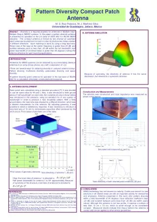
Proposed antenna configuration (a) back view(b) front view Antenna Design: The configuration comprises of two CMA's resonating in TM11 and TM02 modes and operating at 2 GHz. They are placed back-to-back at a separation of d = 2.5cm (the thickness of typical handsets) as shown. The antennas are mounted in such a way so as to match the polarisation.
PRINTER/PLOTTER SOURCE HP 83651B DISPLAY/PROCESSOR HP 8510C SYSTEM BUS RF INPUT HP 8514B S-PARAMETER TEST SET 20 MHz PORT 1 IF/DETECTOR PORT 2 RECTANGULAR WAVEGUIDE CAVITY RESONATOR
The figure indicates considerable reduction in the SAR in the quadrant facing the user. This region forms a zone of silence where the user's head can be located
The CMA resonating in the fundamental TM11 mode radiates a broad side directed beam, whereas the higher order TM02 and TM21 modes radiate with a null in the broad side direction. Since the area of a TM21mode CMA is nearly 35% less than that of a TM02mode CMA, this mode is made use of in reducing the radiation towards the user's head. The combined antenna configuration gives a bandwidth of 4.7%. Experimental Results:
bi-directional radiation pattern required for mobile telephony is achieved by placing two microstrip antennas back-to-back at a separation comparable to the thickness of typical handsets
Conclusions • A quite Zone is formed using the null in the pattern of the higher order mode. • The use of microstrip antennas result in a compact Handsets. • Highly recommended for reducing the radiation hazards to the user