Download
1 / 25
250 likes | 425 Vues
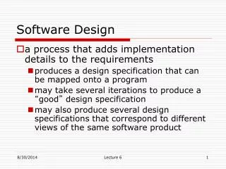
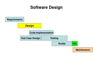
Software Design Methods. Overview. Software Goals Why design software before coding it? How should software be designed? Pseudo-code Flow charts State machines How should software be coded (written)? Useful books

E N D
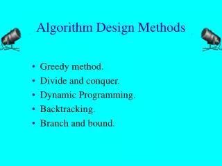
Overview • Software Goals • Why design software before coding it? • How should software be designed? • Pseudo-code • Flow charts • State machines • How should software be coded (written)? • Useful books • The Practice of Programming, Brian W. Kernighan & Rob Pike, Addison Wesley, 1999 • Real-Time Systems Development, Rob Williams, Butterworth-Heinemann/Elsevier, 2006
Software Goals • Simplicity – software is short and simple • Clarity – software is easy for humans and machines to understand • Generality – software can be used for a broad range of situations
Why Design First? “He who fails to plan, plans to fail” “Poor planning produces predictably poor performance” • Software offers tremendous flexibility in implementing systems • Many methods work OK for small programs, but few of these work fine for large or real-time programs • Easy to choose a method which does not scale well to large programs • Starting coding early forces designer to make implementation decisions early, before understanding impact on rest of system (and other programmers) • Even in programs of moderate size, the details obscure the larger picture (“Can’t see the forest for the trees”) • “What are the independent processes within this system?” • “Who else can modify this variable?” • “How often will this function run?” • “How quickly will the system respond?” • Companies which don’t design their software before coding spend much more time and money debugging code, assuming they stay in business long enough to start selling the product
Software Design Representations • Pseudocode • Easy to write but vague • Flow Chart • Good for describing an algorithm: steps in processing, with conditional (if-else) and repeated (loop) execution • State machine • Good for describing system with multiple states (operating modes) and transition rules
Pseudo Code • Pseudo code is written in English to describe the functionality of a particular software module (subroutine) • Include name of module/subroutine, author, date, description of functionality of module, and actual steps • Often you can take the pseudo code and use them lines in your program as comments • Avoid a very fine level of detail (although this may sometimes be difficult to do) • Avoid writing code – use English, not assembly language (or higher-level language) instructions
Pseudo Code Example • Subroutine: Measure_IR_Level • Purpose: Determine infrared light level by reading phototransistor. • Assumes: I/O pin set up as analog input. Analog to digital converter set up in one-shot mode. • Author: Joe Programmer, 3/15/2007 • Set ADC multiplexer to phototransistor channel • Wait for multiplexer to settle • Start conversion • Wait for conversion to finish • Read phototransistor channel result register from ADC • Compute light level based on result • Return light level
Decision? Yes No Input/ Output Flowchart • Shows flow of control in a processing activity (what gets done) • Used to show steps in a process, including decision-making • Does not scale well: becomes confusing if larger than a page Do a Task START END
Flowchart for Process Depth • Executes each time a complete NMEA 0183 sentence arrives through Sonar UART (#0) • Rely on that Receive ISR to detect end of sentence Start U0RxQ Decode NMEASentence Data In Y Invalid? N Update CurDepth Data Out End
Flowchart for Process Position and Save Start • Executes each time a complete NMEA 0183 sentence arrives through GPS UART (#2) • Rely on that Receive ISR to detect end of sentence U2RxQ Decode NMEASentence Data In Y Invalid? N Update CurPos Data Out Y Skip? N Write toDataFlash Update MemUsed Data Out End
Flowchart for Download Data • Executes each time U2TxQ becomes empty (determined by U2 Tx ISR) Start Done with download? Y N Tx Queue full? Y N ReadDataFlash U2TxQ Enqueue Data Out End
What is State-Based Behavior? • System is in exactly one of multiple possible states. State: • time at which system is stable • with constant output conditions • awaiting valid trigger events • A transition between states is triggered by a specific event or events (typically from an input) • Transitions may have associated activities (processing, output) • Guard conditions may prevent transition from occurring, despite event occurence • Finite State Diagram (FSD) specifies all states and transitions • Mealy vs. Moore • Mealy: activities occur while entering state. Outputs defined by state and transition event. • Moore: activities occur within state or while leaving state. Outputs defined only by current state.
Triggering Transitions • Many different trigger sources possible • Time delay passes – use a timer peripheral, or rely on a scheduler • “Advance to the next state in 30 ms” • Event occurs – use the peripheral’s interrupt, or rely on a scheduler • “Analog to digital conversion completes” • “A character is received on UART0” • “User presses switch 3” • Trigger events may be a specific combination of input data values, internal status, and current time • Useful to document trigger events in table • Need to prioritize if multiple simultaneous trigger events are possible
State Transition Representations • State diagram • Intuitive - reveals overall behavior of system (if not too complex) • Hard to verify that behavior is specified for all possible inputs • State table • Easy to verify that behavior is specified for all possible inputs • Obscures overall behavior of system
Fault Example: Traffic Light Controller Opticon (R)L. Ylw OnL. Grn Off State 3 State 2 30 sec.L. Ylw OnL. Grn Off 5 sec. L. Ylw OffL. Red On 2 sec.L. Grn OnL. Red Off Fault State 4 State 1 State 7 StartR. Red On L. Grn On Fault Fault 2 sec.R. Grn OnR. Red Off Fault Fault 5 sec.R. Red OnR. Ylw Off 30 sec. R. Ylw OnR. Grn Off State 5 Opticon (L)R. Ylw OnR. Grn Off State 6
Simplification of Finite State Diagrams • Can use auxiliary variables to reduce number of states • Traffic lights: some similar states exist. Could use a history variable to indicate which direction’s turn it is • Use counter to indicate number of times to transition through sequence of states • Using too many of these variables confuses the reader
Advanced Concepts • Concurrent FSMs • Can have multiple FSMs running in parallel, acting independently or with communication • Hierarchical State Charts • Created to support hierarchical (layered) representation of systems • A state can have a state-machine nested within it • Can also have concurrent FSMs
Building a Finite State Machine • Sequential code (trouble) • Hard to write correctly • Temptations: gotos • Often leads to replicated code • Harder to maintain • Multiple switch/case statements • Easy to code • Gets tougher for larger state machines • Finite state table • Set up table data for all transitions • Requires more sophisticated programming • Very easy to change
Example: State Descriptions and Transitions • Flash LEDs in sequence • Right: red-yellow-green-off • Left: green-yellow-red-off • States • R: only red LED on • Y: only yellow LED on • G: only green LED on • O: all LEDs off Left Left R Y G Right Right Left Left Right O Right
Activities • Use Timer TA0 to trigger state transitions • Configure • Count down in one-shot mode • Generate interrupt when done • Function Set_TA0_Delay() • Load counter with delay value • Enable counting • Start one-shot counting • In each state • Set LEDs correctly • Select next state based on direction • Set timer to trigger next state after interstate delay • Done with state • Also to do in red state • Set direction, interstate delay based on potentiometer • ADC is 10 bits, returns value from 0 to 1023 • If value is < 512 • Direction = left • Delay = (512-value)*scaling factor • If value is >= 512 • Direction right • Delay = (value-511)*scaling factor
How Should Software be Coded? • Code has two requirements • To work • To communicate how it works to the author and others • After the code’s author wins the lottery and quits the company, how hard do you want it to be to pick up the pieces? • Variations in coding styles confuse the reader, so define two aspects of coding style to avoid variation • Syntax • Semantics • So use a Coding Standard or Style Guide to define correct practices • Naming conventions • Memory allocation • Portability • ISRs • Comments • File locations • Eliminates arguments over minor issues
Example Coding Style Guidelines • Names • Use descriptive names for global variables, short names for locals • Use active names for functions (use verbs): Initialize_UART • Be clear what a boolean return value means! Check_Battery vs. Battery_Is_Fully_Charged • Consistency and idioms • Use consistent indentation and brace styles • Use idioms (standard method of using a control structure): e.g. for loop • Use else-if chains for multi-way branches • Expressions and statements • Indent to show structure • Make expressions easy to understand, avoid negative tests • Parenthesize to avoid ambiguity • Break up complex expressions • Be clear: child = (!LC&&!RC)?0:(!LC?RC:LC); is not clear • Be careful with side effects: array[i++] = i++;
Example Coding Style Guidelines • Macros • Parenthesize the macro body and arguments #define square(x) ((x) * (x)) • Magic numbers • Give names to magic numbers with either #define or enum #define MAX_TEMP (551) enum{ MAX_TEMP = 551, /* maximum allowed temperature */ MIN_TEMP = 38, /* minimum allowed temperature */ }; • Use character constants rather than integers: if ch==65 ???? if ch ==‘A’ • Use language to calculate the size of an object: sizeof(mystruct) • Comments • Clarify, don’t confuse • Don’t belabor the obvious • Don’t comment bad code – rewrite it instead • Don’t contradict the code
Example Coding Style Guidelines • Use a standard comment block at the entry of each function • Function Name • Author Name • Date of each modification • Description of what function does • Description of arguments • Pre-conditions • Description of return value • Post-conditions • Defensive programming • Upon entering a function, verify that the arguments are valid • Verify intermediate results are valid • Is the computed value which is about to be returned valid? • Check the value returned by any function which can return an invalid value • No function should be more than 60 lines long, including comments.