Download
1 / 13
130 likes | 216 Vues
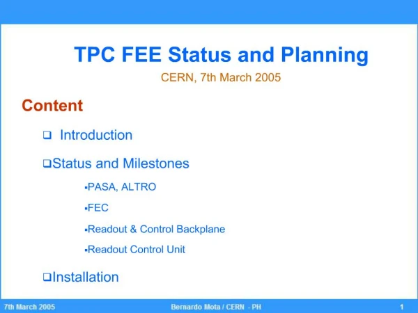
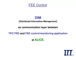
High Level API for the TPC-FEE control and configuration. TPC-FEE ECS/DCS architecture. ECS/DCS mockup. High Level API. DIMM client. ?. bi-directional control and data flow. uni-directional data flow. TCP/IP Ethernet. DDL. DIMM server. DCS Interface module. DDL configuration

E N D
TPC-FEE ECS/DCS architecture ECS/DCS mockup High Level API DIMM client ? bi-directional control and data flow uni-directional data flow TCP/IP Ethernet DDL DIMM server DCS Interface module DDL configuration interface module RCU master
single read • address word • single write • address word • data • multiple read • address word • number of data words to read • multiple write • address word • number of data words • data word 1 • : • data word N • random read • address word 1 • address word 2 • : • address word N • random write • address word 1 • data word 1 • : • address word N • data word N DCS Control Instruction Set
DCS Monitor Instruction Set • Request of attention • address • data word
SIU RCU Functional Overview Configuration Interface Module Data Assembler Module 32 bit FEE1 ALTRO Interface Module RO Sequencer FEE2 RCU Master Module ALTRO Front End Bus L1 Front-End Control Network Interface Module L2 Interrupts RCU bus Trigger Interface Module DCS Interface Module
RCU Master Module • This module resets all other modules when necessary. • It receives triggers and copies the trigger messages from the Trigger module into the Data Assembler Module • It starts the read-out of data via the ALTRO Interface Module and the Data Assembler Module • It handles DCS requests 16 RCU Master Address 32 Data Clk Reset Enable R/W DCS safety message DCS monitor message L1 L2
DDL Configuration Interface Module • This module is used to configure the FECs and the RCUs before starting a run 16 DDL Configuration Interface 40 Address Siu Data 32 Data Clk Reset Enable R/W Transfer Enable
DCS Interface Module • The DCS Interface module sends and receives data from the DCS • Messages are loaded from and stored to memory in the DCS I.M. 16 DCS Interface Address 32 Profibus or Ethernet Data Reset Enable R/W Safety Message Monitoring Message
DCS Interface Module • The RCUs are slaves, but they can generate interrupts to the DCS • The DCS interface devices should work in safety mode with power on the signal cable. • Any request from the DCS should by answered by the RCU within a deterministic time frame, even if the answer is “I am busy”. • A Safety message from the DCS will interrupt the RCU Master. • A Monitoring Message is handled the requested RCU resource is available
Two branches of 1 Gb/s folding out to 2 * 108 RCU connections @ 100Mb/s We can transfer @ 100 Mb/s to level C Level C is done sequentially – One RCU at the time Minimum configuration time assuming 32 Mb/RCU = (12* 32 Mb)/100 Mb/s = 3.9 s A PCI NIC Ethernet DCS Architecture 1 Gb/s Ethernet 1 Gb/s Switch B 9 lines of 100 Mb/s Ethernet 100 Mb/s Switch C 12 lines of 100 Mb/s Ethernet RCU D 9 * 12 Lines = 108 RCUs
Two branches of 1 Gb/s folding out to 2 * 108 RCU connections using Ethernet-to-Profibus gateways We can transfer @ 100 Mb/s to level C Level D is done sequentially in a daisy-chain @ 12Mb/s Minimum configuration time assuming 32 Mb/RCU = (6* 32 Mb)/12 Mb/s = 16 s A PCI NIC Profibus/Ethernet DCS Architecture 1 Gb/s Ethernet 1 Gb/s Switch B 18 lines of 100 Mb/s Ethernet EthernetProfibusGateway C 6 RCUs daisy-chained @ 12Mb/s RCU RCU RCU RCU RCU RCU D
16 PCI-Profibus interfaces, 2 channels per card We can transfer @ 1.2 Mb/s to level B 6 or 7 RCUs are configured sequentially in a daisy-chain Minimum configuration time assuming 32 Mb/RCU = (7* 32 Mb)/1.2 Mb/s = 186 s Profibus DCS Architecture PCI Profibus interfaces A 32 Profibus lines 6(7) RCUs daisy-chained @ 1.2 Mb/s RCU RCU RCU RCU RCU RCU B